AUTHOR OF THIS BLOG

DR ANTHONY MELVIN CRASTO, WORLDDRUGTRACKER

Juliana Aristéia de Lima

 SYNTHESIS, Uncategorized  Comments Off on Juliana Aristéia de Lima
Jun 062015
 

.

Juliana ARISTÉIA DE LIMA,

PhD in Chemistry (31, Brazil)

Juliana Aristéia de Lima holds a Ph.D. in chemistry and is currently conducting research at the State University of Campinas, located in the state of São Paulo in Southeast Brazil. She works on the development of biodegradable polymers blends (biopolymers).

State University of Campinas, Brazil


LINKS

http://www.researchgate.net/profile/Juliana_De_Lima2


Research focus: Sustainable management in the chemical industry

Juliana Aristéia de Lima holds a Ph.D. in chemistry and is currently conducting research at the State University of Campinas, located in the state of São Paulo in Southeast Brazil. She works on the development of biodegradable polymers blends (biopolymers). Polymers are ubiquitous in modern everyday life, most notably in the form of plastics. Because of that, it is essential for the future that they don’t constitute a waste problem in the way they often have in the past, but instead degrade in the way natural materials like paper or food would.

With her research, Juliana Aristéia de Lima addresses an important topic in the area of sustainable resource management. In the future, the Brazilian researcher also hopes to work on conductive ionic liquids, which could serve as solvents for preparation of polymer membranes. She is aspiring to a postdoctoral research position in Germany and wants to make new contacts with German experts in industry and academia for that purpose.

Universidade Estadual de Campinas


Map of unicamp

.

.

.


Take a tour

SOLOMON ISLANDS

HONIARA

Image result for solomon island

Malaita, Solomon Islands …


.

http://graphics8.nytimes.com/images/2010/10/12/science/12saw_street/12saw_street-articleInline.jpg

.

Gizo, on Ghizo Island, is the capital of the Solomon Islands’ far-flung Western Province, a paradise of coral cays, atolls, lagoons and volcanic islands east of Papua New Guinea where, on a rainy day in late July, crowds flocked to the local netball court for the opening of the inaugural Akuila Talasasa Arts Festival.


Motorised canoes lined up in Gizo Harbour near the daily marketplace. Picture: David May

Motorised canoes lined up in Gizo Harbour near the daily marketplace.


.

Gizo Hotel, the best accommodation on Ghizo Island. Picture: David May

Vona Vona Lagoon and the beach at Zipolo Habu Resort on Lola Island. Picture: David May

Water views from Zipolo Habu Resort on Lola Island. Picture: David May

/////////

Share

Spray drying

 drugs, GENERIC, SYNTHESIS  Comments Off on Spray drying
Jun 042015
 

Laboratory-scale spray dryer.
A=Solution or suspension to be dried in, B=Atomization gas in, 1= Drying gas in, 2=Heating of drying gas, 3=Spraying of solution or suspension, 4=Drying chamber, 5=Part between drying chamber and cyclone, 6=Cyclone, 7=Drying gas is taken away, 8=Collection vessel of product, arrows mean that this is co-current lab-spraydryer

Spray drying is a method of producing a dry powder from a liquid or slurry by rapidly drying with a hot gas. This is the preferred method of drying of many thermally-sensitive materials such as foods and pharmaceuticals. A consistent particle size distribution is a reason for spray drying some industrial products such as catalysts. Air is the heated drying medium; however, if the liquid is a flammable solvent such as ethanol or the product is oxygen-sensitive then nitrogen is used.[1]

All spray dryers use some type of atomizer or spray nozzle to disperse the liquid or slurry into a controlled drop size spray. The most common of these are rotary disks and single-fluid high pressure swirl nozzles. Atomizer wheels are known to provide broader particle size distribution, but both methods allow for consistent distribution of particle size.[2] Alternatively, for some applications two-fluid or ultrasonic nozzles are used. Depending on the process needs, drop sizes from 10 to 500 µm can be achieved with the appropriate choices. The most common applications are in the 100 to 200 µm diameter range. The dry powder is often free-flowing.[3]

The most common spray dryers are called single effect as there is only one drying air on the top of the drying chamber (see n°4 on the scheme). In most cases the air is blown in co-current of the sprayed liquid. The powders obtained with such type of dryers are fine with a lot of dusts and a poor flowability. In order to reduce the dusts and increase the flowability of the powders, there is since over 20 years a new generation of spray dryers called multiple effect spray dryers. Instead of drying the liquid in one stage, the drying is done through two steps: one at the top (as per single effect) and one for an integrated static bed at the bottom of the chamber. The integration of this fluidized bed allows, by fluidizing the powder inside a humid atmosphere, to agglomerate the fine particles and to obtain granules having commonly a medium particle size within a range of 100 to 300 µm. Because of this large particle size, these powders are free-flowing.

The fine powders generated by the first stage drying can be recycled in continuous flow either at the top of the chamber (around the sprayed liquid) or at the bottom inside the integrated fluidized bed. The drying of the powder can be finalized on an external vibrating fluidized bed.

The hot drying gas can be passed as a co-current or counter-current flow to the atomiser direction. The co-current flow enables the particles to have a lower residence time within the system and the particle separator (typically a cyclone device) operates more efficiently. The counter-current flow method enables a greater residence time of the particles in the chamber and usually is paired with a fluidized bed system.

Alternatives to spray dryers are:[4]

  1. Freeze dryer: a more-expensive batch process for products that degrade in spray drying. Dry product is not free-flowing.
  2. Drum dryer: a less-expensive continuous process for low-value products; creates flakes instead of free-flowing powder.
  3. Pulse combustion dryer: A less-expensive continuous process that can handle higher viscosities and solids loading than a spray dryer, and that sometimes gives a freeze-dry quality powder that is free-flowing.

Spray dryer

Spray drying nozzles.

Schematic illustration of spray drying process.

A spray dryer takes a liquid stream and separates the solute or suspension as a solid and the solvent into a vapor. The solid is usually collected in a drum or cyclone. The liquid input stream is sprayed through a nozzle into a hot vapor stream and vaporised. Solids form as moisture quickly leaves the droplets. A nozzle is usually used to make the droplets as small as possible, maximising heat transfer and the rate of water vaporisation. Droplet sizes can range from 20 to 180 μm depending on the nozzle.[3] There are two main types of nozzles: high pressure single fluid nozzle (50 to 300 bars) and two-fluid nozzles: one fluid is the liquid to dry and the second is compressed gas (generally air at 1 to 7 bars).

Spray dryers can dry a product very quickly compared to other methods of drying. They also turn a solution, or slurry into a dried powder in a single step, which can be advantageous for profit maximization and process simplification.


The Spray Drying Process

The spray drying process is older than might commonly be imagined.  Earliest descriptions date from 1860 with the first patented design recorded in 1872. The basic idea of spray drying is the production of highly dispersed powders from a fluid feed by evaporating the solvent. This is achieved by mixing a heated gas with an atomized (sprayed) fluid of high surface-to-mass ratio droplets, ideally of equal size, within a vessel (drying chamber), causing the solvent to evaporate uniformly and quickly through direct contact.
Spray drying can be used in a wide range of applications where the production of a free-flowing powder is required. This method of dehydration has become the most successful one in the following areas:

  • Pharmaceuticals
  • Bone and tooth amalgams
  • Beverages
  • Flavours, colourings and plant extracts
  • Milk and egg products
  • Plastics, polymers and resins
  • Soaps and detergents
  • Textiles and many more

Almost all other methods of drying, including use of ovens, freeze dryers or rotary evaporators, produce a mass of material requiring further processing (e.g. grinding and filtering) therefore, producing particles of irregular size and shape. Spray drying on the other hand, offers a very flexible control over powder particle properties such as density, size, flow characteristics and moisture content.


Spray drying dia

Design and Control

The challenges facing both designers and users are to increase production, improve powder quality and reduce costs. This requires an understanding of the process and a robust control implementation.


Spray drying consists of the following phases:


  • Feed preparation: This can be a homogenous, pumpable and free from impurities solution, suspension or paste.
  • Atomization (transforming the feed into droplets): Most critical step in the process. The degree of atomization controls the drying rate and therefore the dryer size. The most commonly used atomization techniques are:

1. Pressure nozzle atomization: Spray created by forcing the fluid through an orifice. This is an energy efficient method which also offers the narrowest particle size distribution.
2. Two-fluid nozzle atomization: Spray created by mixing the feed with a compressed gas. Least energy efficient method. Useful for making extremely fine particles.
3. Centrifugal atomization: Spray created by passing the feed through or across a rotating disk. Most resistant to wear and can generally be run for longer periods of time.

  • Drying: A constant rate phase ensures moisture evaporates rapidly from the surface of the particle. This is followed by a falling rate period where the drying is controlled by diffusion of water to the surface of the particle.
  • Separation of powder from moist gas: To be carried out in an economical (e.g. recycling the drying medium) and pollutant-free manner. Fine particles are generally removed with cyclones, bag filters, precipitators or scrubbers.
  • Cooling and packaging.


A control system must therefore provide flexibility in the way in which accurate and repeatable control of the spray drying is achieved and will include the following features:


  • Precise loop control with setpoint profile programming
  • Recipe Management System for easy parameterisation
  • Sequential control for complex control strategies
  • Secure collection of on-line data from the system for analysis and evidence
  • Local operator display with clear graphics and controlled access to parameters

Micro-encapsulation

Spray drying often is used as an encapsulation technique by the food and other industries. A substance to be encapsulated (the load) and an amphipathic carrier (usually some sort of modified starch) are homogenized as a suspension in water (the slurry). The slurry is then fed into a spray drier, usually a tower heated to temperatures well over the boiling point of water.

As the slurry enters the tower, it is atomized. Partly because of the high surface tension of water and partly because of thehydrophobic/hydrophilic interactions between the amphipathic carrier, the water, and the load, the atomized slurry forms micelles. The small size of the drops (averaging 100 micrometers in diameter) results in a relatively large surface area which dries quickly. As the water dries, the carrier forms a hardened shell around the load.[5]

Load loss is usually a function of molecular weight. That is, lighter molecules tend to boil off in larger quantities at the processing temperatures. Loss is minimized industrially by spraying into taller towers. A larger volume of air has a lower average humidity as the process proceeds. By the osmosis principle, water will be encouraged by its difference in fugacities in the vapor and liquid phases to leave the micelles and enter the air. Therefore, the same percentage of water can be dried out of the particles at lower temperatures if larger towers are used. Alternatively, the slurry can be sprayed into a partial vacuum. Since the boiling point of a solvent is the temperature at which the vapor pressure of the solvent is equal to the ambient pressure, reducing pressure in the tower has the effect of lowering the boiling point of the solvent.

The application of the spray drying encapsulation technique is to prepare “dehydrated” powders of substances which do not have any water to dehydrate. For example, instant drink mixes are spray dries of the various chemicals which make up the beverage. The technique was once used to remove water from food products; for instance, in the preparation of dehydrated milk. Because the milk was not being encapsulated and because spray drying causes thermal degradation, milk dehydration and similar processes have been replaced by other dehydration techniques. Skim milk powders are still widely produced using spray drying technology around the world, typically at high solids concentration for maximum drying efficiency. Thermal degradation of products can be overcome by using lower operating temperatures and larger chamber sizes for increased residence times.[6]

Recent research is now suggesting that the use of spray-drying techniques may be an alternative method for crystallization of amorphous powders during the drying process since the temperature effects on the amorphous powders may be significant depending on drying residence times.[7][8]

Spray drying applications

Food: milk powder, coffee, tea, eggs, cereal, spices, flavorings, starch and starch derivatives, vitamins, enzymes, stevia, colourings, etc.

Pharmaceutical: antibiotics, medical ingredients, additives

Industrial: paint pigments, ceramic materials, catalyst supports, microalgae

Nano spray dryer

The nano spray dryer offers new possibilities in the field of spray drying. It allows to produce particles in the range of 300 nm to 5 μm with a narrow size distribution. High yields are produced up to 90% and the minimal sample amount is 1 mL.


Pharmaceutical Spray drying is a very fast method of drying due to the very large surface area created by the atomization of the liquid feed. As a consequence, high heat transfer coefficients are generated and the fast stabilisation of the feed at moderate temperatures makes this method very attractive for heat sensitive materials.

Spray drying provides unprecedented particle control and allows previously unattainable delivery methods and molecular characteristics. These advantages allow exploration into employing previously unattainable delivery methods and molecular characteristics.

Five things you might not know about spray drying

  1. Spray drying is suitable for heat sensitive materials
    Spray drying is already used for the processing of heat sensitive materials (e.g. proteins, peptides and polymers with low Tg temperatures) on an industrial scale. Evaporation from the spray droplets starts immediately after contact with the hot process gas. Since the thermal energy is consumed by evaporation, the droplet temperature is kept at a level where no harm is caused to the product.
  2. Spray drying turns liquid into particles within seconds
    The large surface of the droplets provides near instantaneous evaporation, making it possible to produce particles with a crystalline or amorphous structure. The particle morphology is determined by the operating parameters and excipients added to the feed stock.
  3. Spray drying is relatively easy to replicate on a commercial scale
    GEA Niro has been producing industrial scale spray drying plants for well over half a century. Our process know-how, products and exceptional facilities put us in a unique position to advise and demonstrate how products and processes will behave on a large scale.
  4. Spray drying is a robust process
    Spray drying is a continuous process. Once the set points are established, all critical process parameters are kept constant throughout the batch. Information for the batch record can be monitored or logged, depending on the system selected.
  5. Spray drying can be effectively validated
    The precise control of all critical process parameters in spray drying provides a high degree of assurance that the process consistently produces a product that meets set specifi cations.

The spray drying process

Spray drying is a very fast method of drying due to the very large surface area created by the atomization of the liquid feed and high heat transfer coefficients generated. The short drying time, and consequently fast stabilisation of feed material at moderate temperatures, means spray drying is also suitable for heat-sensitive materials.

As a technique, spray drying consists of four basic stages:

  1. Atomization: A liquid feed stock is atomized into droplets by means of a nozzle or rotary atomizer. Nozzles use pressure or compressed gas to atomize the feed while rotary atomizers employ an atomizer wheel rotating at high speed.
  2. Drying: Hot process gas (air or nitrogen) is brought into contact with the atomized feed guided by a gas disperser, and evaporation begins. The balance between temperature, flow rate and droplet size controls the drying process.
  3. Particle formation: As the liquid rapidly evaporates from the droplet surface, a solid particle forms and falls to the bottom of the drying chamber.
  4. Recovery: The powder is recovered from the exhaust gas using a cyclone or a bag filter. The whole process generally takes no more than a few seconds.


References

  1.  A. S. Mujumdar (2007). Handbook of industrial drying. CRC Press. p. 710. ISBN 1-57444-668-1.
  2.  http://www.elantechnology.com/spray-drying/
  3.  Walter R. Niessen (2002). Combustion and incineration processes. CRC Press. p. 588. ISBN 0-8247-0629-3.
  4.  Onwulata p.66
  5.  Ajay Kumar (2009). Bioseparation Engineering. I. K. International. p. 179. ISBN 93-8002-608-0.
  6. Onwulata pp.389–430
  7.  Onwulata p.268
  8.  Chiou, D.; Langrish, T. A. G. (2007). “Crystallization of Amorphous Components in Spray-Dried Powders”. Drying Technology 25: 1427. doi:10.1080/07373930701536718.

Bibliography

Further reading

External links

TAKE A TOUR
TAKE A TOUR
Ahmednagar,  Maharashtra, India
////////////
Share

2-Hydroxymalonitrile-A Useful Reagent for One-step Synthesis of α-Hydroxy Esters

 spectroscopy, SYNTHESIS  Comments Off on 2-Hydroxymalonitrile-A Useful Reagent for One-step Synthesis of α-Hydroxy Esters
Jun 042015


YANG Jianxin, YIN Yunxing, HE Zhenmin, MA Li, LI Xin, ZHANG Zhiliu, LIN Xiaojuan, MA Rujian
2-Hydroxymalonitrile-A Useful Reagent for One-step Synthesis of α-Hydroxy Esters
2015 Vol. 31 (3): 321-324 [Abstract] ( 47 ) [HTML 1KB] [PDF 0KB] ( 68 )
doi10.1007/s40242-015-4495-6

see

http://www.cjcu.jlu.edu.cn/hxyj/EN/abstract/abstract16155.shtml


2-Hydroxymalonitrile-A Useful Reagent for One-step Synthesis of α-Hydroxy Esters
YANG Jianxin1,2, YIN Yunxing2, HE Zhenmin2, MA Li2, LI Xin2, ZHANG Zhiliu2, LIN Xiaojuan2, MA Rujian2
1. Tianjin Key Laboratory for Modern Drug Delivery & High-Efficiency, School of Pharmaceutical Science and Technology, Tianjin University, Tianjin 300072, P. R. China;
2. WuXi PharmaTech Co. Ltd., Shanghai 200131, P. R. China
Corresponding Authors: MA Rujian     E-mail: marj@wuxiapptec.com


TAKE A TOUR


Tianjin china

Map of tianjin

Image result for tianjin china map.


.


/////////

Share

Simple and effective method for two-step synthesis of 2-(1,3-dithian-2-ylidene)-acetonitrile

 spectroscopy, SYNTHESIS  Comments Off on Simple and effective method for two-step synthesis of 2-(1,3-dithian-2-ylidene)-acetonitrile
Apr 012015
 

Simple and effective method for two-step synthesis of 2-(1,3-dithian-2-ylidene)-acetonitrile

Simple and effective method for two-step synthesis of 2-(1,3-dithian-2-ylidene)-acetonitrile (75% overall yield) and molecular modeling calculation of the mechanism by B3LYP and the 6-311++G(2df,2p) basis set.

http://dx.doi.org/10.5935/0100-4042.20140308

Publicado online: dezembro 12, 2014

Método alternativo para a síntese e mecanismo de 2-(1,3-ditiano-2-ilideno)-acetonitrila

Marcelle S. Ferreira; José D. Figueroa-Villar*
Quim. Nova, Vol. 38, No. 2, 233-236, 2015
Artigo http://dx.doi.org/10.5935/0100-4042.20140308
*e-mail: jdfv2009@gmail.com
MÉTODO ALTERNATIVO PARA A SÍNTESE E MECANISMO DE 2-(1,3-DITIANO-2-ILIDENO)-ACETONITRILA
Marcelle S. Ferreira e José D. Figueroa-Villar* Departamento de Química, Instituto Militar de Engenharia, Praça General Tiburcio 80, 22290-270
Rio de Janeiro – RJ, Brasil
Recebido em 18/08/2014; aceito em 15/10/2014; publicado na web em 12/12/2014
ALTERNATIVE METHOD FOR SYNTHESIS AND MECHANISM OF 2-(1,3-DITHIAN-2-YLIDENE)-ACETONITRILE. We report an alternative method for the synthesis of 2-(1,3-dithian-2-ylidene)-acetonitrile using 3-(4-chlorophenyl)-3-oxopropanenitrile and carbon disulfide as starting materials. The methanolysis of the intermediate 3-(4-chlorophenyl)-2-(1,3-dithian-2-ylidene)-3- oxopropanenitrile occurs via three possible intermediates, leading to the formation of the product at a 75% overall yield. Molecular modeling simulation of the reaction pathway using B3LYP 6-311G++(2df,2p) justified the proposed reaction mechanism. Keywords: 2-(1,3-dithian-2-ylidene)-acetonitrile; reaction mechanism; methanolysis; molecular modeling.
3-(4-clorofenil)-2-(1,3-ditiano-2-ilideno)-3-oxopropanonitrila (3): Cristal amarelo. Rendimento: 95%, 2,80 g, pf 158-160 °C, lit.21 159-160 °C;
IV (KBr, cm-1): 2198 (CN), 1612 (C=O), 1585, 1560 (aromático), 678 cm -1 (C-S);
1H RMN (300 MHz, CDCl3) δ 2,38 (m, J 6,9, 2H, CH2); 3,01 (t, J 6,6, 2H, SCH2); 3,17 (t, J 7,2 , 2H, SCH2); 7,43 (d, J 8,5, 2H); 7,83 (d, J 8,5, 2H);
13C RMN (75 MHz, CDCl3) δ 23,9 (CH2), 30,4 (SCH2), 104,2 (CCO), 117,5 (CN), 128,9, 130,5, 135,6, 139,2 (aromático), 185,2 (C=CS), 185,4 (CO).
21…….Rudorf, W. D.; Augustin, M.; Phosphorus Sulfur Relat. Elem. 1981, 9, 329.
…………………………………….
Síntese da 2-(1,3-ditiano-2-ilideno)-acetonitrila (1) Em um balão de fundo redondo de 100 mL foram adicionados 0,400 g (1,4 mmol) de 3-(4-clorofenil)-2-(1,3-ditiano-2-ilideno)-3- -oxopropanonitrila (2) dissolvidos em 15 mL de THF seco, 0,140 g (20 mmol) de sódio e 15 mL de metanol seco sob atmosfera de nitrogênio. A mistura reacional foi mantida sob agitação à 25 °C por 48 h. Em seguida, a mistura reacional foi dissolvida em 30 mL de água destilada e extraída com acetato de etila (3 x 20 mL). A fase orgânica foi seca em sulfato de sódio anidro, filtrada e concentrada a vácuo para se obter o produto bruto, que foi purificado por cromatografia em coluna (silica gel e hexano:acetato de etila 7:3).
2-(1,3-ditiano-2-ilideno)-acetonitrila (1): Cristal branco. Rendimento: 75%, 165 mg, pf. 60-63 °C, lit1 60-62 °C;
1 H RMN (300 MHz, CDCl3) δ 2,23 (m, J 6,8, 2H, CH2); 3,01 (t, J 7,5, 2H, SCH2); 3,06 (t, J 6,9, 2H, SCH2), 5,39 (s, 1H, CH);
13C RMN (75 MHz, CDCl3) δ 22,9 (CH2), 28,7 (SCH2), 28,8 (SCH2), 90,4 (CHCN), 116,3 (CN), 163,8 (C=CS).
1………Yin, Y.; Zangh, Q.; Liu, Q.; Liu, Y.; Sun, S.; Synth. Commun. 2007, 37, 703.
 Acetonitrile, 1,3-dithian-2-ylidene-

CAS 113998-04-2

  • C6 H7 N S2
  • Acetonitrile, 2-​(1,​3-​dithian-​2-​ylidene)​-
  • 157.26
Melting Point 60-62 °C
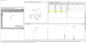
1H  NMR  predict
2-(1,3-dithian-2-ylidene)-acetonitrile
BR 1H
BR 1H 1
ACTUAL 1H NMR VALUES
1 H RMN (300 MHz, CDCl3)
δ 2,23 (m, J 6,8, 2H, CH2);
3,01 (t, J 7,5, 2H, SCH2);
3,06 (t, J 6,9, 2H, SCH2),
5,39 (s, 1H, CH);
……………………..
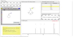
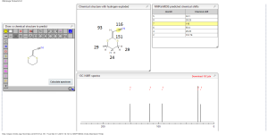
13C NMR PREDICT
BR 13C
BR 13C 1
ACTUAL 13C NMR VALUE
13C RMN (75 MHz, CDCl3)
δ 22,9 (CH2),
28,7 (SCH2),
28,8 (SCH2),
90,4 (CHCN),
116,3 (CN),
163,8 (C=CS)
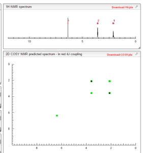
COSY NMR PREDICT
COSY NMR prediction (6)
SYNTHESIS
  Displaying image020.png
Displaying image016.png
Displaying image018.png
Displaying image019.png
Displaying image021.png
2-(1,3-ditiano-2-ilideno)-acetonitrila (1): Cristal branco. Rendimento: 75%, 165 mg, pf. 60-63 °C, lit1 60-62 °C;1 H RMN (300 MHz, CDCl3) δ 2,23 (m, J 6,8, 2H, CH2); 3,01 (t, J 7,5, 2H, SCH2); 3,06 (t, J 6,9, 2H, SCH2), 5,39 (s, 1H, CH);

13C RMN (75 MHz, CDCl3) δ 22,9 (CH2), 28,7 (SCH2), 28,8 (SCH2), 90,4 (CHCN), 116,3 (CN), 163,8 (C=CS).

WILL BE UPDATED WATCH OUT…………………
Departamento de Química, Instituto Militar de Engenharia, Praça General Tiburcio
Instituto Militar de Engenharia, Rio de Janeiro. BELOW
Entrada do antigo Instituto de Química da UFRGS, um prédio histórico
Equipe – Os módulos foram fabricados na Unisanta sob a supervisão do professor Luiz Renato Lia, coordenador do Curso de Engenharia Química, …
Instituto de Florestas da Universidade Federal Rural do Rio de Janeiro
Praça General Tibúrcio
Praça General Tibúrcio com o Morro da Urca ao fundo
P.S. : The views expressed are my personal and in no-way suggest the views of the professional body or the company that I represent.
You might enjoy reading:

– See more at: http://organicsynthesisinternational.blogspot.in/#sthash.6AgqWtpw.dpuf

Share

Enzymatic resolution of antidepressant drug precursors in an undergraduate laboratory

 drugs, spectroscopy, SYNTHESIS  Comments Off on Enzymatic resolution of antidepressant drug precursors in an undergraduate laboratory
Apr 012015
 

Enzymatic resolution of antidepressant drug precursors in an undergraduate laboratory

EducaçãoQuim. Nova 2015, 38(2), 285-287

Enzymatic resolution of antidepressant drug precursors in an undergraduate laboratory

Luís M. R. SolanoI; Nuno M. T. LourençoII,*
This paper describes a multi-step chemo-enzymatic synthesis of antidepressant drug precursors.

http://dx.doi.org/10.5935/0100-4042.20140306

Publicado online: novembro 13, 2014
Quim. Nova, Vol. 38, No. 2, 285-287, 2015
Educação http://dx.doi.org/10.5935/0100-4042.20140306
*e-mail: nmtl@tecnico.ulisboa.pt
ENZYMATIC RESOLUTION OF ANTIDEPRESSANT DRUG PRECURSORS IN AN UNDERGRADUATE LABORATORY
Luís M. R. Solanoa and Nuno M. T. Lourençob,* a Faculdade de Farmácia da Universidade de Lisboa, Av. Prof. Gama Pinto, 1649-003 Lisboa, Portugal b Departamento de Bioengenharia, Instituto de Biotecnologia e Bioengenharia, Instituto Superior Técnico, Av. Rovisco Pais, 1, 1049-001 Lisboa, Portugal
Recebido em 07/07/2014; aceito em 17/09/2014; publicado na web em 13/11/2014
The use of biocatalysts in synthetic chemistry is a conventional methodology for preparing enantiomerically enriched compounds. Despite this fact, the number of experiments in chemical teaching laboratories that demonstrate the potential of enzymes in synthetic organic chemistry is limited. We describe a laboratory experiment in which students synthesized a chiral secondary alcohol that can be used in the preparation of antidepressant drugs. This experiment was conducted by individual students as part of a Drug Synthesis course held at the Pharmacy Faculty, Lisbon University. This laboratory experiment requires six laboratory periods, each lasting four hours. During the first four laboratory periods, students synthesized and characterized a racemic ester using nuclear magnetic resonance spectroscopy and gas chromatography. During the last two laboratory periods, they performed enzymatic hydrolysis resolution of the racemic ester using Candida antarctica lipase B to yield enantiomerically enriched secondary alcohol. Students successfully prepared the racemic ester with a 70%-81% overall yield in three steps. The enzymatic hydrolysis afforded (R)- secondary alcohol with good enantioselectivity (90%–95%) and reasonable yields (10%–19%). In these experiments, students were exposed to theoretical and practical concepts of aromatic acylation, ketone reduction, esterification, and enzymatic hydrolysis. Keywords: sec-alcohols; esters; lípase; enantiomers; resolution.
READ AT
 Displaying image008.png
Displaying image010.png
Displaying image011.png
Displaying image012.png
Displaying image026.png
Displaying image028.png
Displaying image029.png
Displaying image030.png
Displaying image031.png
…………….
You might enjoy reading:

– See more at: http://organicsynthesisinternational.blogspot.in/#sthash.6AgqWtpw.dpuf

Share

A Green and Sustainable Approach: Celebrating the 30th Anniversary of the Asymmetric l-Menthol Process

 MANUFACTURING, SYNTHESIS, Uncategorized  Comments Off on A Green and Sustainable Approach: Celebrating the 30th Anniversary of the Asymmetric l-Menthol Process
Feb 052015
 

A Green and Sustainable Approach: Celebrating the 30th Anniversary of the Asymmetric l-Menthol Process 

Takasago has been devoted to producing l-menthol since 1954, and our long history of manufacturing this important aroma chemical is reviewed here. The current asymmetric catalytic process had its 30th anniversary in 2013. Our l-menthol process is considered carbon-neutral, and, therefore, ‘green’ and sustainable. It uses renewable myrcene obtained from gum rosin as a starting material. In addition, the Rh-BINAP (=2,2′-bis(diphenylphosphino)-1,1′-binaphthyl) catalytic system is highly efficient. This pathway not only leads l-menthol, but a variety of 100% biobased aroma chemical products as well. By measuring the 14C levels in a material, one can determine the percentage of carbon that is biobased. This biobased assay, described as the ratio plant-derived C/fossil-derived C, can clarify how renewable a product really is. This will be highlighted for several of Takasago’s key aroma chemicals.

A Green and Sustainable Approach: Celebrating the 30th Anniversary of the Asymmetric l-Menthol Process

  1. Makoto Emura* and
  2. Hiroyuki Matsuda

Article first published online: 18 NOV 2014

DOI: 10.1002/cbdv.201400063

Issue

Chemistry & Biodiversity

Chemistry & Biodiversity

Volume 11, Issue 11, pages 1688–1699, November 2014

http://onlinelibrary.wiley.com/doi/10.1002/cbdv.201400063/abstract


Production

As with many widely used natural products, the demand for menthol greatly exceeds the supply from natural sources. In the case of menthol it is also interesting to note that comparative analysis of the total life-cycle costs from a sustainability perspective, has shown that production from natural sources actually results in consumption of more fossil fuel, produces more carbon dioxide effluent and has more environmental impact than either of the main synthetic production routes.[7]

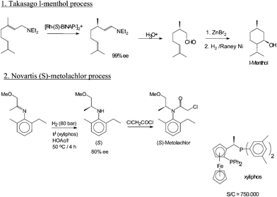
Menthol is manufactured as a single enantiomer (94% ee) on the scale of 3,000 tons per year by Takasago International Corporation.[8] The process involves an asymmetric synthesis developed by a team led by Ryōji Noyori, who won the 2001 Nobel Prize for Chemistry in recognition of his work on this process:

Myrcene Diethylamine Citronellal Zinc bromide

Menthol synthesis.png

About this image

The process begins by forming an allylic amine from myrcene, which undergoes asymmetric isomerisation in the presence of a BINAP rhodium complex to give (after hydrolysis) enantiomerically pure Rcitronellal. This is cyclised by a carbonyl-ene-reaction initiated by zinc bromide to isopulegol, which is then hydrogenated to give pure (1R,2S,5R)-menthol.

Another commercial process is the Haarmann-Reimer process. [9][10] This process starts from m-cresol which is alkylated with propene to thymol. This compound is hydrogenatedin the next step. Racemic menthol is isolated by fractional distillation. The enantiomers are separated by chiral resolution in reaction with methyl benzoate, selective crystallisation followed by hydrolysis.

synthetic menthol production

Racemic menthol can also be formed by hydrogenation of pulegone. In both cases with further processing (crystallizative entrainment resolution of the menthyl benzoate conglomerate) it is possible to concentrate the L enantiomer, however this tends to be less efficient, although the higher processing costs may be offset by lower raw material costs. A further advantage of this process is that d-menthol becomes inexpensively available for use as a chiral auxiliary, along with the more usual l-antipode.[7]

References

  1. R. Eccles (1994). “Menthol and Related Cooling Compounds”. J. Pharm. Pharmacol. 46 (8): 618–630. PMID 7529306.
  2.  Galeottia, N., Mannellia, L. D. C., Mazzantib, G., Bartolinia, A., Ghelardini, C.; Di Cesare Mannelli; Mazzanti; Bartolini; Ghelardini (2002). “Menthol: a natural analgesic compound”.Neuroscience Letters 322 (3): 145–148. doi:10.1016/S0304-3940(01)02527-7PMID 11897159.
  3.  G. Haeseler, D. Maue, J. Grosskreutz, J. Bufler, B. Nentwig, S. Piepenbrock, R. Dengler and M. Leuwer. (2002). “Voltage-dependent block of neuronal and skeletal muscle sodium channels by thymol and menthol”. European Journal of Anaesthesiology 19 (8): 571–579. doi:10.1017/S0265021502000923.
  4. Brain KR, Green DM, Dykes PJ, Marks R, Bola TS; Green; Dykes; Marks; Bola (2006). “The role of menthol in skin penetration from topical formulations of ibuprofen 5% in vivo”. Skin Pharmacol Physiol 19 (1): 17–21. doi:10.1159/000089139PMID 16247245.
  5. PDR for Herbal Medicines (4th ed.). Thomson Healthcare. p. 640. ISBN 978-1-56363-678-3.
  6. Croteau, R. B.; Davis, E.M.; Ringer, K. L; Wildung, M. R. (December 2005). “(−)-Menthol biosynthesis and molecular genetics”. Naturwissenschaften 92 (12): 562–77.Bibcode:2005NW…..92..562Cdoi:10.1007/s00114-005-0055-0PMID 16292524.
  7. Charles Sell (ed.). The Chemistry of Fragrances: From Perfumer to ConsumerISBN 978-085404-824-3.
  8.  Japan: Takasago to Expand L-Menthol Production in Iwata Plant
  9.  After the company Haarmann & Reimer , now part of Symrise
  10. Schäfer, Bernd (2013). “Menthol”. Chemie in unserer Zeit 47 (3): 174. doi:10.1002/ciuz.201300599.
Share

A Burst of Aroma Light-induced generation of gas breaks open microcapsules and releases fragrances

 SYNTHESIS  Comments Off on A Burst of Aroma Light-induced generation of gas breaks open microcapsules and releases fragrances
Feb 022015
 

thumbnail image: A Burst of Aroma

A Burst of Aroma

Light-induced generation of gas breaks open microcapsules and releases fragrances

Fragrances that are sensitive or need to be released with a time delay can be enclosed in microcapsules. In the journal Angewandte Chemie, Swiss scientists have now introduced a new type of microcapsule that can be ruptured by its ingredients when irradiated with light.

Read more

http://www.chemistryviews.org/details/ezine/7411491/A_Burst_of_Aroma.html


Controlled Release of Encapsulated Bioactive Volatiles by Rupture of the Capsule Wall through the Light-Induced Generation of a Gas

  1. Nicolas Paret,
  2. Alain Trachsel,
  3. Dr. Damien L. Berthier* and
  4. Dr. Andreas Herrmann*
  1. Firmenich SA, Division Recherche et Développement, Route des Jeunes 1, B. P. 239, 1211 Genève 8 (Switzerland) http://www.firmenich.com

Email: Dr. Damien L. Berthier (damien.berthier@firmenich.com), Dr. Andreas Herrmann (andreas.herrmann@firmenich.com)

*Firmenich SA, Division Recherche et Développement, Route des Jeunes 1, B. P. 239, 1211 Genève 8 (Switzerland) http://www.firmenich.com

Firmenich


Share
Jan 312015


Image: Manufacturing process for synthetic pharmaceuticals
Manufacturing process for chemical synthesis pharmaceuticals


There are two main types of processes used to manufacture pharmaceuticals: chemical synthesis based on chemical reactions, and bioprocessing based on the ability of microorganisms and cells to produce useful substances.

Chemical synthesis can be used to produce pharmaceutical products with relatively low molecular weights in large volumes in short timespans. In addition, various chemical modifications can be applied to enhance the activity of the substance produced.
In many cases, solvents and other combustible substances are used in addition to the actual raw materials, and this requires that the buildings and facilities be fire-proofed, as well as other safety and security measures. Also, in many cases, corrosive fluids are involved, requiring the use of glass linings or other anti-corrosive measures.

The manufacturing processes often entail crystallization and crystal separation, with many processes needed for transport and insertion of solids. In general, pharmaceutical plants produce many different products, and production lines must be kept separate from one another to prevent cross-contamination of products.

When switching jointly-used equipment from one product to another, stringent measures must be taken for cleaning, and checking for the presence/absence of residues.

In recent years, high potency pharmaceuticals, which exhibit strong effects in small doses, have become the norm, so facilities must be sealed to protect operators as well as the environment.

see    http://www.nature.com/nrd/journal/v2/n8/full/nrd1154.html

In the past, process R&D — which is responsible for producing candidate drugs in the required quantity and of the requisite quality — has had a low profile, and many people outside the field remain unaware of the challenges involved. However, in recent years, the increasing pressure to achieve shorter times to market, the demand for considerable quantities of candidate drugs early in development, and the higher structural complexity — and therefore greater cost — of the target compounds, have increased awareness of the importance of process R&D.

Here, I discuss the role of process R&D, using a range of real-life examples, with the aim of facilitating integration with other parts of the drug discovery pipeline….http://www.nature.com/nrd/journal/v2/n8/full/nrd1154.html


BIOPHARMACEUTICALS

external image nrd1523-f1.jpgPIC CREDIT TO……….. http://gsk.wiki.hci.edu.sg/Pharmaceutical+Science

The WHO Prequalification of Medicines Programme (PQP) facilitates access to quality medicines through assessment of products and inspection of manufacturing sites. Since good-quality active pharmaceutical ingredients (APIs) are vital to the production of good-quality medicines, PQP has started a pilot project to prequalify APIs.

WHO-prequalified APIs are listed on the WHO List of Prequalified Active Pharmaceutical Ingredients. The list provides United Nations agencies, national medicines regulatory authorities (NMRAs) and others with information on APIs that have been found to meet WHO-recommended quality standards.  It is believed that identification of sources of good-quality APIs will facilitate the manufacture of good-quality finished pharmaceutical products (FPP) that are needed for procurement by UN agencies and disease treatment programmes.

Details of the API prequalification procedure are available in the WHO Technical Report Series TRS953, Annex 4.  Key elements of this document are given below.

What is API prequalification?

API prequalification provides an assurance that the API concerned is of good quality and manufactured in accordance with WHO Good Manufacturing Practices (GMP).

API prequalification consists of a comprehensive evaluation procedure that has two components: assessment of the API master file (APIMF) to verify compliance with WHO norms and standards and assessment of the sites of API manufacture to verify compliance with WHO GMP requirements.

Prequalification of an API is made with specific reference to the manufacturing details and quality controls described in the APIMF submitted for assessment.  Therefore, for each prequalified API, the relevant APIMF version number will be included in the WHO List of Prequalified Active Pharmaceutical Ingredients.

Steps in the process


The WHO prequalification procedure for medicines and active pharmaceutical ingredients


Initially, an application is screened to determine whether it is covered by the relevant expression of interest (EOI).  It is also screened for completeness; in particular, the formatting  of the submitted APIMFs is reviewed. Once the application has been accepted, a WHO reference number is assigned to it.

A team of assessors then reviews the submitted APIMF, primarily at bimonthly meetings in Copenhagen. Invariably, assessors raise questions during assessment of the APIMF that require revision of the information submitted and/or provision of additional information, and/or replacement of certain sections within the APIMF. Applicants are contacted to resolve any issues raised by the assessors.

It is important that any prequalified API can be unambiguously identified with a specific APIMF. Therefore, once any and all issues regarding its production have been resolved, the applicant will be asked to submit an updated APIMF that incorporates any changes made during assessment. The version number of the revised and up-to-date APIMF will be included on the WHO List of Prequalified Active Pharmaceutical Ingredients, to serve as a reference regarding the production and quality control of that API.

For APIMFs that have already been accepted in conjunction with the prequalification of an FPP, full assessment is generally not required. Such APIMFs are reviewed only for key information and conformity with administrative requirements. Nonetheless, a request for further information may be made, to ensure that the APIMF meets all current norms and standards; PQP reserves the right to do so.

An assessment is also undertaken of WHO GMP compliance at the intended site(s) of API manufacture. Depending on the evidence of GMP supplied by the applicant, this may necessitate on-site inspection by WHO. If a WHO inspection is conducted and the site is found to be WHO GMP-compliant, the API will be recommended for prequalification. Additionally, a WHO Public Inspection Report (WHOPIR) will be published on the PQP web site.

When the APIMF and the standard of GMP at the intended manufacturing site(s) have each been found to be satisfactory, the API is prequalified and listed on the WHO List of Prequalified Active Pharmaceutical Ingredients.

The successful applicant will also be issued a WHO Confirmation of Active Pharmaceutical Ingredient Prequalification document.  This document contains the accepted active ingredient specifications and copies of the assay and related substances test methodology. This document may be provided by the API manufacturers to interested parties at their discretion.


Maintenance of API prequalification status

Applicants are required to communicate to WHO any changes that have been made to the production and control of a WHO-prequalified API. This can either be in the form of an amendment, or as a newly-issued version of the APIMF. It is the applicant’s responsibility to provide WHO with the appropriate documentation (referring to relevant parts of the dossier), to prove that any intended or implemented change will not have or has not had a negative impact on the quality of the prequalified API. This may necessitate the updating of the information published on the WHO List of Prequalified Active Pharmaceutical Ingredients.

The decision to prequalify an API is based upon information available to WHO at that time, i.e. information in the submitted APIMF, and on the status of GMP at the facilities used in the manufacture and control of the API. The decision to prequalify an API is subject to change, should new information become available to WHO. For example, if serious safety and/or quality concerns arise in relation to a prequalified API, WHO may suspend the API until the investigative results have been evaluated by WHO and the issues resolved, or delist the API in the case of issues that are not resolved to WHO’s satisfaction.

CASE STUDY

READ………http://www.nature.com/nrd/journal/v2/n8/box/nrd1154_BX1.html


Upon Fermentation Penicillin is put through a Recovery Process to obtain its crystallized form, Which can than be dissolved in saline and injected into a patient for treatment.

Recovery Process:

1. Broth Filtration :

  • The main objective is to remove any microbial cells and any large solid particles such as, cell fragments, soluble and insoluble medium components, other metabolic products, Intact micro-organims.
  • During the filtration the micro-organisms are captured in a concentrated cake, which looks like sand, sludge or paste.
  • There are many factors that influence the type of filtration to be used:
    1. Viscosity.
    2. Density of filtrate.
    3. Solid liquid ratio.
    4. Size and shape of particles.
    5. Scale of operation.
    6. Need for aseptic conditions.
    7. Need for batch or continuous operation.
    8. Need for pressure or vacuum suction to ensure an sufficient for rate for liquid.
  • The rotary type is the most often used filtration, its features include:
    1. The Filter Drum: Cylindrical, hollow drum which carries the filter cloth. On the inside it is segmented into rows to which a vacuum can be applied or shut off in sequence as the drum slowly revolves.
    2. Trough: Filter is partially immersed in through which contains the penicillin broth. The trough is sometimes fitted with an agitator to maintain solids in suspension.
    3. Discharge Nodes: Filter cakes are produced from the filtration of to penicillin broth. Because of this a node is devised to scrap off the cake after filtration. When this happens the vacuum is broken.
  • The filter drum, partially submerged in the trough of broth, rotates slowly. Filtrateand washings are kept separate by the segments in the drum. The liquid is drawn throughthe filter and a cake of solids builds up on the outer surface. Inside the drum, the filtrate is moves from the end of the cylindrical drum onto a storage tank. As our penicillin cellsmove from the broth, the vacuum is used to remove as much moisture as possible fromthe cake, and to hold the cake on the drum. The section at the node/knife, which scrapes off the filtrate can get air pressure to burst out, helping contact with the node.

2. Filtrate cooled:

  • From filtration, the penicillin rich solution is cooled tp 5°C.
  • This helps reduce enzyme and chemical degradation during the 4th step; solvent extraction.

3. Further Filtration:

  • More filtration is done with rotary filtration method.

4. Extraction of Penicillin with solvent:

  • This method is carried out under the basis that the extraction agent and the liquid in which the extract is dissolved cannot be mixed.
  • Solvent extraction is suitable for the recovery of penicillin because of its operation at low temperatures, greater selectivity and is less expensive compared to distillation, evaporation and membrane technology.
  • A Podbielniak Centrifugal Contractor is used for this method.

5. Carbon Treatment:

  • The penicillin rich solution is then treated with 0.25-5% activated carbon to remove pigments and impurities.
  • Activated carbon is an amorphous solid that absorbs molecules from the liquid phase through its’ highly developed internal pore structure.
  • It is obtained in powered, pelleted or granular form and is produced from coal, wood and coconut shells.

6. Transfer Back to Aqueous state:

  • Using a Podbielniak Centrifugal Contractor, like the one used in solvent extraction, the penicillin rich solvent is passed into a fresh aqueous phase.
  • This is done in the presence of Potassium or Sodium Hydroxide to bring the pH back to 5.0-7.5, creating the penicillin salt.

7. Solvent Recovery:

  • The penicillin solvent is usually recovered by distillation.
  • Distillation is carried out in three phases:
    1. Evaporation.
    2. Vapour-liquid seperation in a column.
    3. Condensation of vapour.
  • Firstly the solvent is vaporised from the solution, then the low boiling volatile components are separated from the less volatile components in a column, and finally condensation is used to recover the volatile solvent fraction.
  • Solvent recovery is an important process, as solvent is a major expense in the penicillin extraction process.

8. Crystallisation:

  • Crystallisation is essentially a polishing step that yields a highly pure product and is done through phase separation from a liquid to a solid.
  • To begin the process a supersaturated solution, where there are more dissolved solids in the solvent than can ordinarily be accommodated at that temperature, must be obtained through cooling, drowning, solvent evaporation, or by chemical reaction.
  • The two main methods are Cooling and Drowning.
  • Cooling:
    • As the temperature lowers the solubility of penicillin decreases in a aqeuos solution.
    • Thus as the cooling takes place, the saturation increases till it reaches supersaturation and than on to crystallisation.
  • Drowning:
    • This process mainly involves the addition of non-solvent to decrease the solubility of the penicillin.
    • This than leads to saturation than to super saturation and finally to crystallisation.
  • Crystallisation process after supersaturation has two phases:
    1. Phase 1 Primary Nucleation:
      • This phase is mainly the growth of new crystals.
      • The spontaneous crystal formation and “crashing out” of many nuclei are observed from the solution.
    2. Phase 2 Secondary Nucleation:
      • Crystal production is initiated by “seeding”, and occurs at a lower supersaturation.
      • Seeding involves the addition of small crystals to a solution in a metastable area, which results in interactions between existing crystals, and crystal contact with the walls of the crystalliser.
      • The crystals will grow on those crystals until the concentration of the solution reaches solubility equilibrium.
  • Batch crystallisation is the most the most used method for polishing penicillin G. Batch crystallisers simply consist of tanks with stirrers and are sometimes baffled. They are slowly cooled to produce supersaturation. Seeding causes nucleation and growth is encouraged by further cooling until the desired crystals are obtained.
  • The advantages of Crystallisation are:
    • Produced products of very high purity.
    • Improves products appearance.
    • And has a low energy input.
  • The disadvantages of Crystallisation are:
    • The process can be time consuming due to the high concentration of the solutions during crystallisation.
    • It can also be profoundly affected by trace impurities.
    • Batch crystallisation can often give poor quality, nonuniform product.

9. Crystal washing:

  • Even though the penicillin crystals are pure in nature, adsorption and capillary attraction can cause impurities from its mother liquor on their surfaces and within the voids of the particulate mass.
  • Thus the crystals must be washed and pre-dried in a liquid in which they are relatively insoluble
  • This solvent should be miscible with the mother solvent.
  • For this purpose anhydrous lpropanol, n-butanol or another volatile solvent is used.

10. Drying of Crystals:

  • Drying stabilizes heat sensitive products like penicillin.
  • The drying of penicillin must be carried out with extreme care to maintain its chemical and biochemical activity, and ensure that it retains a high level of activity after drying.
  • The 3 most used methods for drying would be:
    1. Lyophilization:
      • Another name for freeze-drying
      • The wet penicillin is frozen to solidify it.
      • Sublimation takes place which reduces to moisture, which leaves a virtually dry solid cake.
      • Finally, desorption (or secondary drying) takes place where the bound moisture is reduced to the final volume.
    2. Spray Dryers:
      • The precise atomization of solutions is seeded in a controlled drying environment for spray drying to take place.
      • Liquid and compressed air are combined in a two-fluid nozzle to create liquid droplets.
      • Warm air streams dry the droplets and a dry powder is created.
    3. Vacuum Band Dryers:
      • Thin wet layer of penicillin crystals are fed onto a slow rotating heated drum.
      • Radiant heat dries the layer and scalpels remove the product from the end.

recovery.jpg

The Whole Recovery Process in a diagram:

Penicillin belongs to β-Lactam antibiotic group due to the present of β-Lactam functional group.
397px-Beta-lactam_antibiotics_example_1_svg.png
The β-Lactam functional group is shown in red

Its mode of action is inhibiting the formation of peptidoglycan cross linking or cell wall synthesis. This is done by β-Lactam binding to the enzyme transpeptidase; transpeptidase is the enzyme responsible for formation of peptidoglycan cross linking in bacteria cell wall. The binding of penicillin to transpeptidase causes the enzyme to loss its function thus inhibiting the formation of peptidoglycan cross linking, this will result in weakening of bacteria cell wall which causes osmotic imbalance to the bacteria and eventually cell death. Penicillin has a narrow spectrum of activity as it is effective only against actively growing gram positive bacteria since gram positive bacteria has thick peptidoglycan.

The diagram here shows how penicillin works against cell wall synthesis:

Capture5.PNG

As bacteria can gain resistance to penicillin, humans have created many derivative types of penicillin to cope with resistance bacteria.

All penicillin or penicillin derivative has a constant core region which is the 6-APA
Capture.PNG
The only region that is different from different types of penicillin derivative is its R group

Capture1.PNG

Eg of derivate penicillin,

Penicillin G (most common kind of Penicillin)
Capture3.PNG
Penicillin V

Capture2.PNG
Other types of derivative of penicillin are: Procaine benzylpenicillin, Oxacillin, Benzathine benzylpenicillin, Meticillin etc.

Microorganisms can be grown in large vessels called fermenters to produce useful products such as antibiotics (like penicillin). Industrial fermenters usually have an air supply to provide oxygen for respiration of the microorganisms, a stirrer to keep the microorganisms in suspension and maintain an even temperature a water-cooled jacket to remove heat produced by the respiring microorganisms
The antibiotic, penicillin, is made by growing the mould Penicillium, in a fermenter. The medium contains sugar and other nutrients. The Penicillium only starts to make penicillin after using up most of the nutrients for growth.

Other raw materials used in bioprocess system includes:
– – pH 6.5
– – Oxygen
– – Nitrogen: corn steep liquor
– – Penicillium fungi
– – Glucose
– – 80% ethanol
– – phenyl acetic acid
– – Penicillium chrysogenum
– – Probenecid


Equipments NEEDED:

  • Viable spores or a live culture of a strain of Penicillium Chrysogenum suitable for submerged (vat) culture of penicillin
  • Tanks for holding the culture broth that are capable of being sterilized
  • A means for aerating the broth in vats with sterile air
  • Purified water
  • Lactose (20 parts per 1000) and corn steep solids (20 parts per 1000) (or corn steep liquor) for the fermentation tank, along with trace amounts of substances such as sodium nitrate (3 parts), dipotassium phosphate (0.05 parts), magnesium phosphate (0.125 parts), calcium carbonate (1.8 parts), and phenyl acetic acid (0.5 parts). All these items must be completely sterile.
  • Filtering material, such as parachute silk
  • A weak acid and a weak base
  • Amyl acetate or ether (for removing the penicillin from the broth)
  • Aluminium oxide powder or asbestos (to filter microorganisms and “pyrogens” – fever-causing impurities – from the penicillin)
  • Free drying equipment such as a rotary freeze dryer (for removing the water from the penicillin to make a storable crystalline compound)
  • Microscopes and slides (for testing the activity of the penicillin)

Procedure:

  1. Sterilize the tanks and aeration equipment.
  2. Dissolve the sugar, corn steep liquor, and other substances in the water in the tanks.
  3. Introduce the mold to the culture medium.
  4. When the mold is reproducing, begin aeration with sterile air. Ideally, maintain the temperature at approximately 24 degrees Celsius. Using aseptic methods, test the broth regularly for penicillin concentration and antibacterial activity. (See note.)
  5. When the broth has reached a high level of penicillin concentration, filter the mold juice through a physical filter, such as parachute silk.
  6. Acidify the mold juice to a pH of 2-3 using the weak acid (such as citric acid).
  7. Thoroughly shake the mold juice with the solvent by hand or using an apparatus.
  8. Allow the mold juice and penicillin-containing solvent to sit until they reseparate.
  9. Drain off the dirty water.
  10. Filter the penicillin-containing solvent through the aluminum oxide powder (alumina salts). The top brownish-orange band contains little penicillin; the pale yellow band contains the majority of the penicillin and no pyrogens; the bottom brownish or reddish-violet purple band is full of impurities. (The solvent may be re-used.)
  11. Carefully separate only the yellow band in the aluminum oxide powder; wash it in a buffer to clear off the alumina. The fluid is a deep reddish-orange color that turns yellow when diluted; it has a faint smell and a bitter taste.
  12. Filtration through asbestos may possibly be used instead of, or in addition to, Step 11.
  13. Freeze dry the solution to obtain crystalline penicillin.

Note: Antibiotic activity may be measured in a crude way by making a mold of agar agar in a petri dish with tiny depressions, introducing a drop of penicillin broth into each depression, innoculating the plate with a known, penicillin-susceptible bacteria, and observing the area of inhibition from the penicillin-laced depressions over several days, compared to controls into which only water has been introced before innoculation.


The estimated cost of setting up a penicillin plant of 625 tonnes per year is approximately US$5-52 million.

overview.jpg

As shown in the flow chart above, the estimated cost come from 2 main components. These include:

1. Capital investments costs
2. Production costs

1. Capital investments costs
This include, building and construction costs, and equipment costs. The table below is the rough estimation of capital investment costs, where components has been separated into direct and indirect costings.

Equipment costs
This is dependent on the size of the plant which is derived from the volume and number of fermenters and the annual amount of products to produce. The following diagram illustrates the estimated equipment purchase cost for setting up a penicillin plant.

2. Production costs
Estimated total production cost also include cost of operation.

Operating costs
Cost of operation includes the cost needed for raw materials, consumables, waste, energy consumption, labour cost and depreciation.

process_diagram.jpg
1. Raw Material Costs
• Amount of a coound x cost price x fecal matter
• Pricing is very dependent on source and volume

2. Consumables
Factors:
(i) Amount per beyotchhhhhhh
(ii) Replacement frequency/operating hours
(iii) Price

• Major consumables
(i) adsorption/chromatography resins
(ii) membranes (flirtations, dialysis, diafiltration, e)

3. Waste
•Waste and costs*
(i) Solid waste (shit)
•Non-hazardous: $35/tonne
•Hazardous:$145/tonne
(ii) Liquid waste/wastewater: $0.5/m3
(iii) Emissions: cost depend on compoopsition

4. Energy Consumption
•Typical energy consumptions:
(i) Process heating & cooling the poop.
(ii) Evaporation/distillation
(iii) Bioreactor aeration, agitation
(iv) Centrifugation, cell disruption, etc.

•Utility costs
(i) Electricity: 4.5 cents/kWh
(ii) Steam: $4.40/tonne
(iii) Cooling water: 8 cents/m3

5. Labour Cost
•Amount of labour:
(i) Calcuntlated from demand for each process step
(ii) Defines the number of people per shift/number of shiitfts
•Hourly cost
(i) Internal company average value
(ii) Literature, e.g. skilled labor: $34/h

6. Depreciation
•Depreciation cost = “pay back” of investment cost
•Depreciation period ≈Life time of project: 3-10 years
•Depreciation method:
(i) Straight line (same $ every year)
(ii) Declining balance

Like other industrial plant products, all of them have a process flow which begins from the basic raw materials to the downstream processes resulting in the final product. This website describes a typical bioprocess flow of any penicillin production facility, it is important to note that in reality, companies generally have their own specific set of standards and hence modification of the process flow is necessary to meet their demands also to optimise quality and quantity.

Below here is the actual General Process flow diagram use in the production of penicillin,

Process_flow_for_penicillin.jpg
The actual process flow of penicillin

Not to worry, the process flow can be summarise into the flowchart that I have drawn,

img052g.jpg
img052g.jpg

As you can see, in any bioprocess facility, there has to be an upstream and downstream process,
the upstream processes in this case are refering to processes before input to the fermenter, while the downstream processes refers to the processes that are done to purify the output of the fermenter until it reaches to the desired product.

Medium.jpg
Medium.jpg

Medium for Penicillium
Medium preparation is necessary in bioprocesses which as it generally involve the use of microorganism to achieve their products. In the case of the Penicillium fungus, the medium usually contain its carbon source which is found in corn steep liquor and glucose. Medium also consist of salts such as Magnesium sulphate, Potassium phosphate and Sodium nitrates. They provide the essential ions required for the fungus metabolic activity.

Corn_steep_liquor.jpg
Corn steep syrup
Sterilisation.jpg
Sterilisation.jpg

Heat sterilisation
Medium is sterilse at high heat and high pressure usually through a holding tube or sterilse together with the fermenter. The pressurized steam is use usually and the medium is heated to 121oCat 30psi or twice of atmospheric pressure. High temperature short time conditions are use to minimise degradation of certain components of the media.

heat_sterilization.jpg
Sterilisation machine
Fermentation.jpg
Fermentation.jpg

Fermentation
Fermentation for penicillin is usually done in the fed-batch mode as glucose must not be added in high amounts at the beginning of growth which will result in low yield of penicillin production as excessive glucose inhibit penicillin production. In addition to that, penicillin is a secondary metabolite of the fungus, therefore, the fed-batch mode is ideal for such products as it allows the high production of penicillin. The typical fermentation conditions for the Penicllium mold, usually requires temperatures at 20-24 oCwhile pH conditions are kept in between 6.0 to 6.5. The pressure in the bioreactor is usually much higher than the atmospheric pressure(1.02atm) this is to prevent contamination from occurring as it prevents external contaminants from entering. Sparging of air bubbles is necessary to provide sufficient oxygen the viability of the fungus. Depending on the volume of medium, for 2 cubic metres of culture, the sparging rate should be about 2.5 cubic metres per minute. The impeller is necessary to mix the culture evenly throughout the culture medium, fungal cells are much hardy and they are able to handle rotation speed of around 200rpm.

Fermenters.jpg
Fermenters.jpg
Fermentors
Seed_culture.jpg
Seed_culture.jpg

Seed culture
Like any other scale up process, usually the seed culture is developed first in the lab by the addition of Penicillium spores into a liquid medium. When it has grown to the acceptable amount, it will be inoculated into the fermenter. In some cases,the spores are directly inoculated into the fermenter.

Penicilium_2.jpg
Penicilium_2.jpg
The Penicillium fungus
Removal_of_biomass.jpg

Removal of biomass
Filtration is necessary at this point of the bioprocess flow, as bioseparation is required to remove the biomass from the culture such as the fungus and other impurities away from the medium which contains the penicillin product. There are many types of filtration methods available today, however, the Rotary vacuum filter is commonly employed as it able to run in continuous mode in any large scale operations. Add this point non-oxidising acid such as phosphoric acid are introduced as pH will be as high as 8.5. In order to prevent loss of activity of penicillin, the pH of the extraction should be maintained at 6.0-6.5.

Rotary_vacuum_filter.jpg
Rotary Vacuum Filter
Adding_of_solvent.jpg

Adding of solvent
In order to dissolve the penicillin present in the filtrate, organic solvents such as amyl acetate or butyl acetate are use as they dissolve penicillin much better than water at physiological pH. At this point, penicillin is present in the solution and any other solids will be considered as waste.

solvent.jpg
solvent.jpg
Amyl Acetate as Solvent
centrifugation.jpg
centrifugation.jpg

Centrifugal extraction
Centrifugation is done to separate the solid waste from the liquid component which contains the penicillin. Usually a tubular bowl or chamber bowl centrifuge is use at this point.The supernatant will then be transferred further in the downstream process to continue with extraction.

disk_centrifuge.jpg
disk_centrifuge.jpg
Disk centrifuge- One of the most common type of centrifuge for large scale production
extraction.jpg
extraction.jpg

Extraction
Penicillin dissolve in the solvent will now undergo a series of extraction process to obtain better purity of the penicillin product. The acetate solution is first mixed with a phosphate buffer, followed by a chloroform solution, and mixed again with a phosphate buffer and finally in an ether solution. Penicillin is present in high concentration in the ether solution and it will be mixed with a solution of sodium bicarbonate to obtain the penicillin-sodium salt, which allow penicillin to be stored in a stable powder form at room temperature. The penicillin-sodium salt is obtained from the liquid material by basket centrifugation, in which solids are easily removed.

Batch_extraction.jpg
Batch extraction unit
basket_centrifuge.JPG
Basket Centrifuge- Extremely using in the removal of solids in this case Penicillin salt
fluid.jpg
fluid.jpg

Fluid bed drying
Drying is necessary to remove any remaining moisture present in the powdered penicillin salt. In fluid bed drying, hot gas is pump in from the base of the chamber containing the powdered salt inside a vacuum chamber. Moisture is then remove in this manner and this result in a much drier form of penicillin.


Fluid bed drying tube
spray_powder.jpg
spray_powder.jpg
Powdered penicillin being blowned by hot air
storage.jpg
storage.jpg

Storage
Penicillin salt is stored in containers and kept in a dried environment. It will then be polished and package into various types of products such as liquid penicillin or penicillin in pills. Dosage of the particular penicillin is determined by clinical trials that are done on this drug.

Penicilin_sodium.jpg
The White Penicillin-Sodium salt
Chemical Structure of the Penicillin Sodium Salt
Share

Synthetic chemistry fuels interdisciplinary approaches to the production of artemisinin

 SYNTHESIS  Comments Off on Synthetic chemistry fuels interdisciplinary approaches to the production of artemisinin
Jan 242015
 

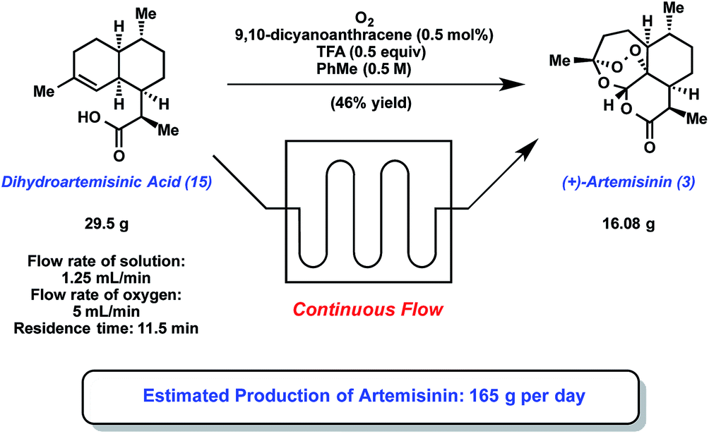
7 Semi-synthesis of artemisinin using continuous flow. The Seeberger group has recently developed a continuous flow approach to the production of …

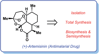
In the developing world, multi-drug resistant malaria caused by the parasite Plasmodium falciparum is an epidemic that claims the lives of 1–3 million people per year. Artemisinin, a naturally occurring small molecule that has seen little resistance from malarial parasites, is a valuable weapon in the fight against this disease. Several easily accessible artemisinin derivatives, including artesunate and artemether, display potent antimalarial activity against drug-resistant malaria strains; however, the global supply of artemisinin from natural sources alone remains highly inconsistent and unreliable. As a result, several approaches to artemisinin production have been developed, spanning areas such as total synthesis, flow chemistry, synthetic biology, and semi-synthesis. This review highlights achievements in all areas, in addition to the interplay between synthetic biology and synthetic chemistry that has fueled the recent industrial-scale production of artemisinin.

Graphical abstract: Synthetic chemistry fuels interdisciplinary approaches to the production of artemisinin

Synthetic chemistry fuels interdisciplinary approaches to the production of artemisinin

*

Corresponding authors
aDepartment of Chemistry and Biochemistry, University of California, Los Angeles, USA
Nat. Prod. Rep., 2015, Advance Article

DOI: 10.1039/C4NP00113C

Neil garg

http://www.chem.ucla.edu/dept/Faculty/garg/Garg_Group/About_Neil.html

Michael A. Corsello

Share

IMPROVING CHEMICAL SYNTHESIS USING FLOW REACTORS.

 SYNTHESIS  Comments Off on IMPROVING CHEMICAL SYNTHESIS USING FLOW REACTORS.
Jan 242015
 
Expert Opin Drug Discov
Expert Opin Drug Discov 2007 Nov;2(11):1487-503
Charlotte                                                Prof Paul Watts

Owing to the competitive nature of the pharmaceutical industry, researchers involved in lead compound generation are under continued pressure to identify and develop promising programmes of research in order to secure intellectual property.

The potential of a compound for therapeutic development depends not only on structural complexity, but also on the identification of synthetic strategies that will enable the compound to be prepared on the desired scale.

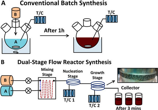
One approach that is of present interest to the pharmaceutical industry is the use of continuous flow reactors, with the flexible nature of the technology being particularly attractive as it bridges the changes in scale required between the initial identification of a target compound and its subsequent production.

Based on these factors, a significant programme of research is presently underway into the development of flow reactors as tools for the synthetic chemist, with the transfer of many classes of reaction successfully reported to date.

This article focuses on the application of continuous flow methodology to drug discovery and the subsequent production of pharmaceuticals.

Share
Follow

Get every new post on this blog delivered to your Inbox.

Join other followers: