AUTHOR OF THIS BLOG

DR ANTHONY MELVIN CRASTO, WORLDDRUGTRACKER

Nanopalladium-catalyzed conjugate reduction of Michael acceptors – application in flow

 PROCESS, SYNTHESIS  Comments Off on Nanopalladium-catalyzed conjugate reduction of Michael acceptors – application in flow
Mar 102016


Green Chem., 2016, Advance Article
DOI: 10.1039/C5GC02920A, Communication
Anuja Nagendiran, Henrik Sorensen, Magnus J. Johansson, Cheuk-Wai Tai, Jan-E. Backvall
A continuous-flow approach towards the selective nanopalladium-catalyzed hydrogenation of the olefinic bond in various Michael acceptors, which could lead to a greener and more sustainable process, has been developed.
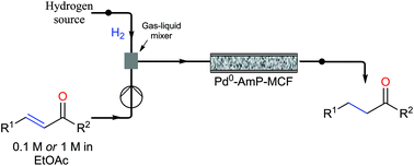
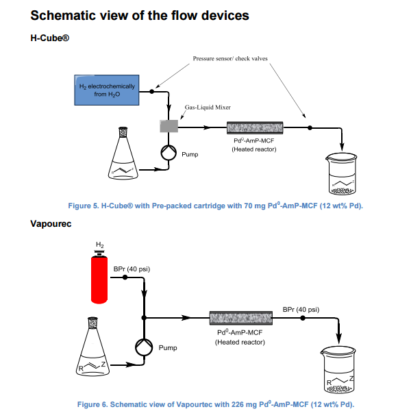
A continuous-flow approach towards the selective nanopalladium-catalyzed hydrogenation of the olefinic bond in various Michael acceptors, which could lead to a greener and more sustainable process, has been developed. The nanopalladium is supported on aminofunctionalized mesocellular foam. Both aromatic and aliphatic substrates, covering a variation of functional groups such as acids, aldehydes, esters, ketones, and nitriles were selectively hydrogenated in high to excellent yields using two different flow-devices (H-Cube® and Vapourtec). The catalyst was able to hydrogenate cinnamaldehyde continuously for 24 h (in total hydrogenating 19 g cinnanmaldehyde using 70 mg of catalyst in the H-cube®) without showing any significant decrease in activity or selectivity. Furthermore, the metal leaching of the catalyst was found to be very low (ppb amounts) in the two flow devices
str1
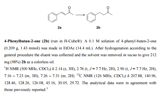
3 Gottlieb, H. E.; Kotlyar, V; Nudelman, A. J. Org. Chem. 1997, 62, 7512-7515.
str1

Nanopalladium-catalyzed conjugate reduction of Michael acceptors – application in flow

*Corresponding authors
aDepartment of Organic Chemistry, Arrhenius Laboratory, Stockholm University, SE-106 91 Stockholm, Sweden
E-mail: jeb@organ.su.se
bBerzelii Centre EXSELENT on Porous Materials, Arrhenius Laboratory, Stockholm University, SE-106 91 Stockholm, Sweden
cAstraZeneca R&D, Innovative Medicines, Cardiovascular and Metabolic Disorders, Medicinal Chemistry, Pepparedsleden 1, SE-431 83 Mölndal, Sweden
dDepartment of Materials and Environmental Chemistry, Arrhenius Laboratory, Stockholm University, SE-106 91, Stockholm, Sweden
Green Chem., 2016, Advance Article

DOI: 10.1039/C5GC02920A

///////

Share

Efficient formation of nitriles in the vapor-phase catalytic dehydration of aldoximes

 PROCESS, SYNTHESIS  Comments Off on Efficient formation of nitriles in the vapor-phase catalytic dehydration of aldoximes
Mar 102016


Efficient formation of nitriles in the vapor-phase catalytic dehydration of aldoximes

Green Chem., 2016, Advance Article
DOI: 10.1039/C6GC00384B, Paper
Daolai Sun, Eisyun Kitamura, Yasuhiro Yamada, Satoshi Sato
Nitriles were efficiently produced in a vapor-phase dehydration of aldoximes over SiO2 catalysts without external heat supply.
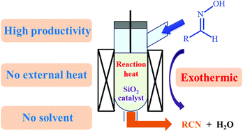
A vapor-phase dehydration of acetaldoxime to acetonitrile was investigated over various solid catalysts. Among the tested catalysts, ZrO2, Al2O3 and SiO2 showed high catalytic activity for the formation of acetonitrile from acetaldoxime, while the correlation between catalytic activity and the acid property of the catalysts was not observed. Weak acidic sites such as silanols sufficiently work as catalytic sites for the dehydration, which does not require strong acids such as zeolites. Several SiO2 catalysts with different physical properties were tested, and the SiO2with the smallest pore size and the highest specific surface area showed the highest catalytic activity for the formation of acetonitrile. Because the dehydration of acetaldoxime to acetonitrile is exothermic, a large amount of reaction heat was generated during the reaction, and the reaction temperature was found to be significantly affected by the feed rate of the reactant and the flow rate of the carrier gas. In order to effectively utilize the in situ generated reaction heat, the dehydration of acetaldoxime to acetonitrile without using the external heat supply was conducted. The temperature was controllable even in the absence of the external heat, and the acetonitrile yield higher than 90% could be achieved in such a green operation under the environment-friendly adiabatic conditions.

Efficient formation of nitriles in the vapor-phase catalytic dehydration of aldoximes

*Corresponding authors
aGraduate School of Engineering, Chiba University, Chiba, Japan
E-mail: satoshi@faculty.chiba-u.jp
Fax: +81 43 290 3401
Tel: +81 43 290 3377
Green Chem., 2016, Advance Article

DOI: 10.1039/C6GC00384B

//////

Share

Pd(II) pincer type complex catalyzed tandem C-H and N-H activation of acetanilide in aqueous media: a concise access to functionalized carbazoles in a single step

 spectroscopy, SYNTHESIS  Comments Off on Pd(II) pincer type complex catalyzed tandem C-H and N-H activation of acetanilide in aqueous media: a concise access to functionalized carbazoles in a single step
Mar 072016
 

Green Chem., 2016, Advance Article
DOI: 10.1039/C5GC02937F, Paper
Vignesh Arumugam, Werner Kaminsky, Dharmaraj Nallasamy
NNO Pincer type Pd(II) complex catalyzed one-pot synthesis of N-acetylcarbazoles in aqueous media is presented.

http://pubs.rsc.org/en/Content/ArticleLanding/2016/GC/C5GC02937F?utm_source=feedburner&utm_medium=feed&utm_campaign=Feed%3A+rss%2FGC+%28RSC+-+Green+Chem.+latest+articles%29#!divAbstract


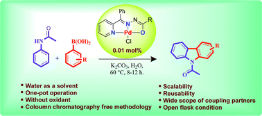
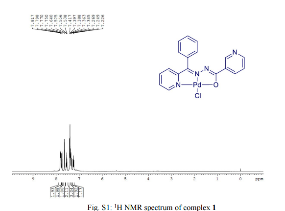
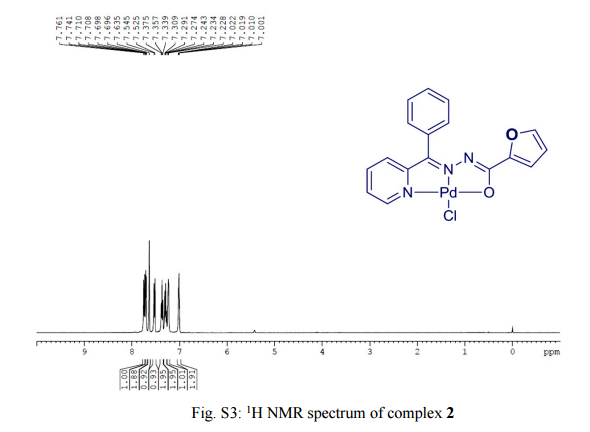
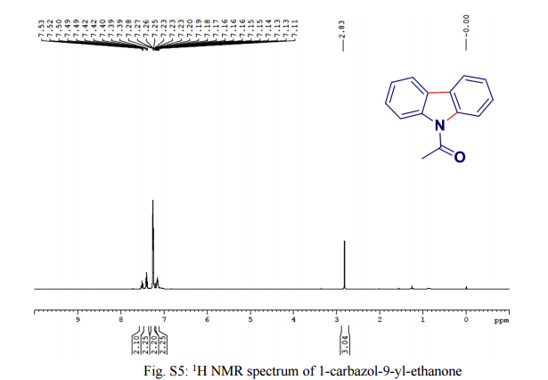
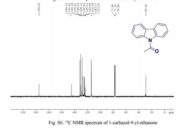
One-pot, tandem C–H and N–H activation of acetanilides with aryl boronic acids to realize functionalized carbazoles was conveniently performed under aerobic conditions using a novelNNO pincer type Pd(II) complex [Pd(L)Cl] (where L = nicotinic acid (phenyl-pyridin-2-yl-methylene)-hydrazide or furan-2-carboxylic acid (phenyl-pyridin-2-yl-methylene)-hydrazide) as a catalyst in neat water and a very low (0.01 mol%) amount of catalyst. It is worth noting that recyclability up to six consecutive runs and column chromatography free isolation of the title heterocycles in an excellent yield are achieved.

str1

str1

str1


str1


str1


str1

Pd(II) pincer type complex catalyzed tandem C–H and N–H activation of acetanilide in aqueous media: a concise access to functionalized carbazoles in a single step

*Corresponding authors
aInorganic & Nanomaterials Research Laboratory, Department of Chemistry, Bharathiar University, Coimbatore 641 046, India
E-mail: dharmaraj@buc.edu.in
Web: http://ndharmaraj.wix.com/inrl
Fax: +91 4222422387
Tel: +91 4222428316
bDepartment of Chemistry, University of Washington, Seattle, USA
Green Chem., 2016, Advance Article

DOI: 10.1039/C5GC02937F

One-pot, tandem C–H and N–H activation of acetanilides with aryl boronic acids to realize functionalized carbazoles was conveniently performed under aerobic conditions using a novelNNO pincer type Pd(II) complex [Pd(L)Cl] (where L = nicotinic acid (phenyl-pyridin-2-yl-methylene)-hydrazide or furan-2-carboxylic acid (phenyl-pyridin-2-yl-methylene)-hydrazide) as a catalyst in neat water and a very low (0.01 mol%) amount of catalyst. It is worth noting that recyclability up to six consecutive runs and column chromatography free isolation of the title heterocycles in an excellent yield are achieved.

////////

Share

Application of On-Line NIR for Process Control during the Manufacture of Sitagliptin

 PROCESS, spectroscopy, SYNTHESIS  Comments Off on Application of On-Line NIR for Process Control during the Manufacture of Sitagliptin
Mar 062016
 
Abstract Image

The transamination-chemistry-based process for sitagliptin is a through-process, which challenges the crystallization of the active pharmaceutical ingredient (API) in a batch stream composed of multiple components. Risk-assessment-based design of experiment (DoE) studies of particle size distribution (PSD) and crystallization showed that the final API PSD strongly depends on the seeding-point temperature, which in turn relies on the solution composition.

To determine the solution composition, near-infrared (NIR) methods had been developed with partial least squares (PLS) regression on spectra of simulated process samples whose compositions were made by spiking each pure component, either sitagliptin free base (FB), water, isopropyl alcohol (IPA), dimethyl sulfoxide (DMSO), or isopropyl acetate (IPAc), into the process stream according to a DoE. An additional update to the PLS models was made by incorporating the matrix difference between simulated samples in lab and factory batches.

Overall, at temperatures of 20–35 °C, the NIR models provided a standard error of prediction (SEP) of less than 0.23 wt % for FB in 10.56–32.91 wt %, 0.22 wt % for DMSO in 3.77–19.18 wt %, 0.32 wt % for IPAc in 0.00–5.70 wt %, and 0.23 wt % for water in 11.20–28.58 wt %. After passing the performance qualification, these on-line NIR methods were successfully established and applied for the on-line analysis of production batches for compositions prior to the seeding point of sitagliptin crystallization.

see……..http://pubs.acs.org/doi/abs/10.1021/acs.oprd.5b00409

Application of On-Line NIR for Process Control during the Manufacture of Sitagliptin

Global Science, Technology and Commercialization, Merck Sharp & Dohme Corporation P.O. Box 2000, Rahway, New Jersey 07065, United States
Org. Process Res. Dev., Article ASAP
DOI: 10.1021/acs.oprd.5b00409
Publication Date (Web): February 12, 2016
Copyright © 2016 American Chemical Society

////

Share

Flow Chemistry: Recent Developments in the Synthesis of Pharmaceutical Products

 PROCESS, SYNTHESIS  Comments Off on Flow Chemistry: Recent Developments in the Synthesis of Pharmaceutical Products
Jan 052016


Abstract Image

Recently, application of the flow technologies for the preparation of fine chemicals, such as natural products or Active Pharmaceutical Ingredients (APIs), has become very popular, especially in academia. Although pharma industry still relies on multipurpose batch or semibatch reactors, it is evident that interest is arising toward continuous flow manufacturing of organic molecules, including highly functionalized and chiral compounds. Continuous flow synthetic methodologies can also be easily combined to other enabling technologies, such as microwave irradiation, supported reagents or catalysts, photochemistry, inductive heating, electrochemistry, new solvent systems, 3D printing, or microreactor technology. This combination could allow the development of fully automated process with an increased efficiency and, in many cases, improved sustainability. It has been also demonstrated that a safer manufacturing of organic intermediates and APIs could be obtained under continuous flow conditions, where some synthetic steps that were not permitted for safety reasons can be performed with minimum risk. In this review we focused our attention only on very recent advances in the continuous flow multistep synthesis of organic molecules which found application as APIs, especially highlighting the contributions described in the literature from 2013 to 2015, including very recent examples not reported in any published review. Without claiming to be complete, we will give a general overview of different approaches, technologies, and synthetic strategies used so far, thus hoping to contribute to minimize the gap between academic research and pharmaceutical manufacturing. A general outlook about a quite young and relatively unexplored field of research, like stereoselective organocatalysis under flow conditions, will be also presented, and most significant examples will be described; our purpose is to illustrate all of the potentialities of continuous flow organocatalysis and offer a starting point to develop new methodologies for the synthesis of chiral drugs. Finally, some considerations on the perspectives and the possible, expected developments in the field are briefly discussed.

Two examples out of several in the publication discussed below……………


1  Diphenhydramine Hydrochloride

Figure
Scheme 1. Continuous Flow Synthesis of Diphenhydramine Hydrochloride
Diphenhydramine hydrochloride is the active pharmaceutical ingredient in several widely used medications (e.g., Benadryl, Zzzquil, Tylenol PM, Unisom), and its worldwide demand is higher than 100 tons/year.
In 2013, Jamison and co-workers developed a continuous flow process for the synthesis of 3minimizing waste and reducing purification steps and production time with respect to existing batch synthetic routes (Scheme 1). In the optimized process, chlorodiphenylmethane 1 and dimethylethanolamine 2 were mixed neat and pumped into a 720 μL PFA tube reactor (i.d. = 0.5 mm) at 175 °C with a residence time of 16 min. Running the reaction above the boiling point of 2and without any solvent resulted in high reaction rate. Product 3, obtained in the form of molten salt (i.e., above the melting point of the salt), could be easily transported in the flow system, a procedure not feasible on the same scale under batch conditions.
The reactor outcome was then combined with preheated NaOH 3 M to neutralize ammonium salts. After quenching, neutralized tertiary amine was extracted with hexanes into an inline membrane separator. The organic layer was then treated with HCl (5 M solution in iPrOH) in order to precipitate diphenhydramine hydrochloride 3 with an overall yield of 90% and an output of 2.4 g/h.

2 Olanzapine

Figure
Scheme 2. Continuous Flow Synthesis of Olanzapine
Atypical antipsychotic drugs differ from classical antipsychotics because of less side effects caused (e.g., involuntary tremors, body rigidity, and extrapyramidal effects). Among atypical ones, olanzapine 10, marketed with the name of Zyprexa, is used for the treatment of schizophrenia and bipolar disorders.
In 2013 Kirschning and co-workers developed the multistep continuous flow synthesis of olanzapine 10 using inductive heating (IH) as enabling technology to dramatically reduce reaction times and to increase process efficiency.(16) Inductive heating is a nonconventional heating technology based on the induction of an electromagnetic field (at medium or high frequency depending on nanoparticle sizes) to magnetic nanoparticles which result in a very rapid increase of temperature.As depicted in Scheme 2 the first synthetic step consisted of coupling aryl iodide 4 and aminothiazole 5 using Pd2dba3 as catalyst and Xantphos as ligand. Buchwald–Hartwig coupling took place inside a PEEK reactor filled with steel beads (0.8 mm) and heated inductively at 50 °C (15 kHz). AcOEt was chosen as solvent since it was compatible with following reaction steps. After quenching with distilled H2O and upon in-line extraction in a glass column, crude mixture was passed through a silica cartridge in order to remove Pd catalyst. Nitroaromatic compound 6 was then subjected to reduction with Et3SiH into a fixed bed reactor containing Pd/C at 40 °C. Aniline 7 was obtained in nearly quantitative yield, and the catalyst could be used for more than 250 h without loss of activity. The reactor outcome was then mixed with HCl (0.6 M methanol solution) and heated under high frequency (800 kHz) at 140 °C. Acid catalyzed cyclization afforded product 8 with an overall yield of 88%. Remarkably, the three step sequence did not require any solvent switch, and the total reactor volume is about 8 mL only.
The final substitution of compound 8 with piperazine 9 was carried out using a 3 mL of PEEK reactor containing MAGSILICA as inductive material and silica-supported Ti(OiPr)4 as Lewis acid. Heating inductively the reactor at 85 °C with a medium frequency (25 kHz) gave Olanzapine 10 in 83% yield.

SEE MORE IN THE PUBLICATION…………..


Flow Chemistry: Recent Developments in the Synthesis of Pharmaceutical Products

Dipartimento di Chimica, Università degli Studi di Milano Via Golgi 19, I-20133 Milano, Italy
Org. Process Res. Dev., Article ASAP
DOI: 10.1021/acs.oprd.5b00325
Publication Date (Web): November 26, 2015
Copyright © 2015 American Chemical Society

ACS Editors’ Choice – This is an open access article published under an ACS AuthorChoice License, which permits copying and redistribution of the article or any adaptations for non-commercial purposes.

Riccardo Porta

Riccardo Porta

 PhD Student
Dipartimento di Chimica, Università degli Studi di Milano Via Golgi 19, I-20133 Milano, Italy

Map of milan italy


//////////

Share

Toward a Large-Scale Approach to Milnacipran Analogues Using Diazo Compounds in Flow Chemistry

 PROCESS, SYNTHESIS  Comments Off on Toward a Large-Scale Approach to Milnacipran Analogues Using Diazo Compounds in Flow Chemistry
Nov 112015


Abstract Image

The safe use of diazo reagents for the preparation of a key structure in the synthesis of milnacipran analogues is described herein. Using continuous flow technology, the diazo reagent is synthesized, purified, dried, and subsequently used in semi-batch mode for an intramolecular cyclopropanation. Side products formed in the reaction are isolated and rationalized to optimize the process. Different separation techniques in flow are compared with regard to their ability to produce pure and dry diazo reagents. The studies yield a scalable process to a key intermediate in the syntheses of milnacipran and its possible substituted analogues.


Toward a Large-Scale Approach to Milnacipran Analogues Using Diazo Compounds in Flow Chemistry

School of Chemistry, Cardiff University, Park Place, Cardiff CF10 3AT, U.K.
Institut de Recherche Pierre Fabre, 81603 Gaillac, France
§ Pierre Fabre Médicament, Parc Industriel de la Chartreuse, 81106 Castres, France
Org. Process Res. Dev., Article ASAP
DOI: 10.1021/acs.oprd.5b00308
Publication Date (Web): October 29, 2015
Copyright © 2015 American Chemical Society
*E-mail: wirth@cf.ac.uk.

http://pubs.acs.org/doi/abs/10.1021/acs.oprd.5b00308


DRUG APPROVALS BY DR ANTHONY MELVIN CRASTO …..FOR BLOG HOME CLICK HERE

Join me on Linkedin

View Anthony Melvin Crasto Ph.D's profile on LinkedIn

Join me on Facebook FACEBOOK

Join me on twitterFollow amcrasto on Twitter
Join me on google plus Googleplus

 amcrasto@gmail.com

/////

Share

Applying Flow Chemistry: Methods, Materials, and Multistep Synthesis

 SYNTHESIS  Comments Off on Applying Flow Chemistry: Methods, Materials, and Multistep Synthesis
Sep 052015
 

Abstract Image


The synthesis of complex molecules requires control over both chemical reactivity and reaction conditions. While reactivity drives the majority of chemical discovery, advances in reaction condition control have accelerated method development/discovery. Recent tools include automated synthesizers and flow reactors. In this Synopsis, we describe how flow reactors have enabled chemical advances in our groups in the areas of single-stage reactions, materials synthesis, and multistep reactions. In each section, we detail the lessons learned and propose future directions.


Applying Flow Chemistry: Methods, Materials, and Multistep Synthesis

Department of Biomolecular Systems, Max Planck Institute of Colloids and Interfaces, Am Mühlenberg 1, 14476 Potsdam, Germany
Institute for Chemistry and Biochemistry, Freie Universität Berlin, Arnimallee 22, 14195 Berlin, Germany
§ Department of Chemistry and Biochemistry, Florida State University, Tallahassee, Florida 32306, United States
J. Org. Chem., 2013, 78 (13), pp 6384–6389
DOI: 10.1021/jo400583m

///////

Share

Telescoping multistep reactions

 PROCESS, SYNTHESIS  Comments Off on Telescoping multistep reactions
Jul 292015


Telescoping multistep reactions

The synthesis of fine chemicals sometimes requires multiple reactions and tedious work-up between each step is often necessary. Purification may involve the addition of a quenching reagent, multiple aqueous and organic extractions, the addition of a drying agent, filtration, evaporation, and further purification by chromatography, distillation, or recrystallization. These operations all require significant input of energy and materials that ultimately end up as large amounts of waste. Methods and technologies that eliminate or simplify one or many of these steps can make a significant influence on the environmental impact of a multistep chemical synthesis. Continuous processing is particularly suitable for ‘telescoping’ reaction sequences, and many methods have been developed to facilitate this.1

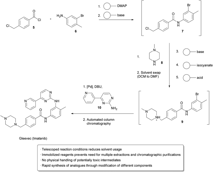
One strategy utilizes solid supported reagents packed into columns which allow starting materials to flow in and product to be collected at the outlet without requiring separation of the spent reagent. Different columns may be linked in series, allowing multistep processes to take place. Extra operations may also be necessary, such as solvent changes or the removal of unwanted side products. Methods for automating these processes have also been developed. An example from the Ley group illustrates many of these technologies in the design of a single apparatus to continuously prepareImatinib (Gleevec) from simple starting materials (Scheme 1).2Acid chloride 5 and aniline 6 in DCM were flowed through a cartridge containing immobilized DMAP as a nucleophilic catalyst, followed by a basic cartridge to scavenge any remaining 5. The formation of the amide 7 was monitored by an in-line UV spectrometer and subsequently added to a vial containing piperazine 8 in DMF at 50 °C, which facilitated evaporation of the DCM. Once a particular amount of 7 was obtained, as indicated by the UV spectrometer, a connected autosampler would collect this solution and pump it through an immobilized base to induce a substitution reaction, followed by an immobilized isonitrile to scavenge any remaining 8. An immobilized acid was used to ‘catch’ amine 9 through protonation, allowing unreacted 7 to go to waste. ‘Release’ of 9 through deprotonation followed by the addition of aniline 10 and a palladium catalyst facilitated a cross-coupling reaction, furnishing the crude Imatinib, which was then evaporated onto a silica gel column for automated chromatography. Pure product was isolated in 32% overall yield and >95% purity. While not explicitly demonstrated, the possibility of using this apparatus to form analogs by using modified starting materials is proposed. The ability to perform multi-step synthesis of pharmaceuticals without handling of the intermediates is particularly interesting, as exposure to these species can be hazardous.


Multistep synthesis of Imatinib (Gleevec).49
Scheme 1 Multistep synthesis of Imatinib (Gleevec).

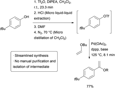
The above example utilizes packed cartridges of scavengers to effect purification. An alternative method is to more closely emulate typical batch purification operations such as distillation andextraction, but on a small, continuous scale. Several different ‘chip’ purification devices have been developed for this purpose.3-12 Some of these technologies were used together in a combined triflation/Heck reaction of phenols (Scheme2). After the initial triflation step in dichloromethane, the product is combined with a stream of aqueous HCl and passed on to a chip containing a membrane that allows the organic phase to pass through while the aqueous stream is passed to waste. The purified triflate then combines with a stream of DMF and the material enters a distillation device heated to 70 °C which allows the volatile dichloromethane to be carried out of the reactor with a stream of nitrogen gas. The product then enters a final reactor where it combines with a stream ofalkene and catalyst to form the Heck product. The whole reactor was operated continuously for 5.5 hours, generating approximately 32 mg of product per hour.


Triflation/Heck coupling facilitated by automated extraction and distillation.64
Scheme 2 Triflation/Heck coupling facilitated by automated extraction and distillation.

Integration of multiple reaction steps, separations, and purifications into one continuous process has great potential for avoiding energy intensive and wasteful intermediate purification. While great progress has been made, the development of a truly general set of reagents, methods, and devices still requires more research. Immobilized reagents can be wasteful to scale up, and there are significant limitations to current microreactor extraction and distillation technologies. Crystallization is another very important technique in pharmaceutical synthesis, and while there are an increasing number of methods for continuous crystallization,14 15 , it is yet to be used as an intermediate purification step in an automated multi-step synthesis. Lastly, large scale applications of such complex, streamlined processes are required before a thorough assessment of their environmental impact in comparison with traditional batch routes can be made.


  1. D. Webb and T. F. Jamison, Chem. Sci., 2010, 1, 675–680
  2. M. D. Hopkin, I. R. Baxendale and S. V. Ley, Chem. Commun., 2010, 46, 2450–2452
  3. J. G. Kralj, H. R. Sahoo and K. F. Jensen, Lab Chip, 2007, 7, 256–263
  4. R. L. Hartman, H. R. Sahoo, B. C. Yen and K. F. Jensen, Lab Chip, 2009, 9, 1843–1849
  5. M. O’Brien, P. Koss, D. L. Browne and S. V. Ley, Org. Biomol. Chem., 2012, 10, 7031–7036
  6. K. K. R. Tetala, J. W. Swarts, B. Chen, A. E. M. Janssen and T. A. van Beek, Lab Chip, 2009, 9, 2085–2092
  7. D. M. Fries, T. Voitl and P. R. von Rohr, Chem. Eng. Technol., 2008, 31, 1182–1187
  8. S. Aljbour, H. Yamada and T. Tagawa, Top. Catal., 2010, 53, 694–699
  9. A. Smirnova, K. Shimura, A. Hibara, M. A. Proskurnin and T. Kitamori, Anal. Sci., 2007, 23, 103–107
  10. R. C. R. Wootton and A. J. deMello, Chem. Commun., 2004, 266–267
  11. A. Hibara, K. Toshin, T. Tsukahara, K. Mawatari and T. Kitamora, Chem. Lett., 2008, 1064–1065
  12. Y. Zhang, S. Kato and T. Anazawa, Lab Chip, 2010, 10, 899–908
  13. R. L. Hartman, J. R. Naber, S. L. Buchwald and K. F. Jensen, Angew. Chem., Int. Ed., 2010, 49, 899–903
  14. S. Lawton, G. Steele, P. Shering, L. Zhao, I. Laird and X.-W. Ni, Org. Process Res. Dev., 2009, 13, 1357–1363
  15. H. Zhao, J.-X. Wang, Q.-A. Wang, J.-F. Chen and J. Yun, Ind. Eng. Chem. Res., 2007, 46, 8229–8235

///////

Share
Jul 282015


Heterogeneous catalysis and catalyst recycling

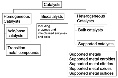
Heterogeneous catalysis is a type of catalysis in which the catalyst occupies a different phase from the reactants and products. This may refer to the physical phase — solid, liquid or gas — but also to immiscible fluids. Heterogeneous catalysts can be more easily recycled than homogeneous, but characterization of the catalyst and optimization of properties can be more difficult.

Heterogeneous catalysis is widely used in the synthesis of bulk and fine chemicals. In a general, small scale batch reaction, the catalyst, reactants, and solvent are stirred together until completion of the reaction, after which the bulk liquid is separated by filtration. The catalyst can then be collected for either recycling or disposal. In a continuous process, the catalyst can be fixed in space and the reaction mixture allowed to flow over it. The reaction and separation are thus combined in a single step, and the catalyst remains in the reactor for easy recycling. Beyond facilitating separation, thecatalyst may have improved lifetime due to decreased exposure to the environment, and reaction rates and turnover numbers can be enhanced through the use of high concentrations of a catalyst with continuous recycling. The benefits of flow are seemingly obvious, yet it has only recently become a widely adopted method for bench-scale synthesis.1

Hydrogenation of ethene on a solid surface

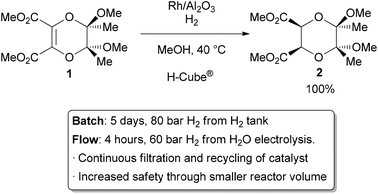
The most common application of continuous heterogeneous catalysis is in hydrogenation reactions,2 where the handling and separation of solid precious metal catalysts is not only tedious but hazardous under batch conditions. Moreover, the mixing between the three phases in a hydrogenation is generally quite poor. The use of a flow reactor gives a higher interfacial area between phases and thus more efficient reactions. For example, Ley and co-workers found that the hydrogenation of alkene 1 to 2 was challenging in batch, requiring multiple days at 80 bar of H2 (Scheme 1).3 Using a commercially available H-Cube® reactor, the reaction time was shortened to 4 hours, the pressure reduced to 60 bar, and manual separation and recycling of the catalyst from the reaction was unnecessary. The increased efficiency is due to a combination of improved mixing of the three phases, as well as the continuous recycling and high local concentration of the catalyst. The H-Cube offers a further safety advantage because it generates hydrogen gas on demand from water, obviating the need for a high pressure H2 tank.

Hydrogenation with an immobilized heterogeneous catalyst.
Scheme 1 Hydrogenation with an immobilized heterogeneous catalyst.

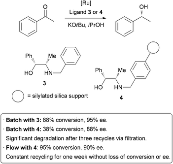
Homogeneous catalysis has many advantages over heterogeneous catalysis, such as increased activity and selectivity, and mechanisms of action that are more easily understood. Unfortunately, the difficulty associated with separating homogeneous catalysts from the product is a significant hindrance to their large scale application. In an attempt to combine the high activity of homogeneous catalysis with the practical advantageous of heterogeneous catalysis, there has been much research into immobilizing homogeneous catalysts on solid supports.4 This is generally achieved by linking thecatalyst to the surface of an insoluble solid such as silica or polymer beads. As was the case in batch hydrogenation reactions, the process of separating and purifying the catalyst is inefficient, potentially dangerous, and may lead to degradation and loss of material. Performing these reactions in a flow system can help overcome these problems.5 A highly efficient example has been demonstrated by van Leeuwen and co-workers, who sought to immobilize a catalyst used in transfer hydrogenation reactions (Scheme 2).6Their test reaction was the asymmetric reduction of acetophenone; homogeneousreduction with ruthenium and ligand 3 provided 88% conversion and 95% enantioselectivity. The ligand was then covalently linked to silica gel through the benzyl group to form 4. Using this heterogenized system under batch conditions, conversion dropped to 38% on the same time scale, and a slight decrease in enantioselectivity occurred. A reduction in activity of a catalyst upon immobilization is common, so highly efficient recycling is required. Unfortunately, when attempting to re-use the catalyst after filtration, significant degradation and leaching occurred. The catalyst was then packed in a glass column for application in flow chemistry. After a short optimization of flow rate, 95% conversion and 90% ee were obtained. Importantly, the reaction could be run continuously for up to one week without significant degradation in conversion or enantioselectivity. The physical isolation of catalyst species on the solid support is suggested to contribute to the long catalystlifetime. Interestingly, the basic potassium tert-butoxide additive was only required initially to activate the catalyst, and the reaction could subsequently be run without additional base, allowing the product to be isolated completely free of additives. It is important to note, on top of the decreased activity due to modification, that leaching from cleavage off the solid support and the increased cost of the catalyst due to derivatization are all potential downsides of immobilization of catalysts. In some instances, a seemingly heterogeneous catalyst has been shown to leach active homogeneous species into solution.7 However, as can be seen above, robust systems can be developed which do combine the best features of both homogeneous and heterogeneous catalysis.

Immobilization of a homogeneous catalyst on a solid support.
Scheme 7 Immobilization of a homogeneous catalyst on a solid support.

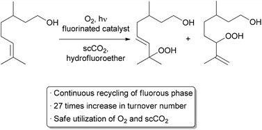
Another important method for recycling expensive catalysts is through the use of liquid–liquid biphasic conditions where the catalyst and reactants can be separated by extraction upon completion of the reaction. Such processes have already been utilized on the medium and large scale in a continuous or semi-continuous fashion.8,9 Recycling on a small scale is typically done through batch liquid–liquid extractions, but examples using continuous methods are increasing.10-13 A recent automated small scale recycling of a biphasic catalyst system was demonstrated by the George group in the continuous oxidation of citronellol (Scheme 3).14A highly fluorinated porphyrin was used as the photocatalyst, and a combination of hydrofluoroether (HFE) and scCO2 was used as the solvent. Under high pressure flow conditions, a single phase was observed. Depressurization occurred after the reactor, resulting in two phases – the organic product in one, and the catalyst and HFE in the other. The denser, catalyst-containing fluorous phase was continuously pumped back through the reactor. With this method, the catalyst was recycled 10 times while maintaining 75% of its catalytic activity, giving an increase in TON of approximately 27-fold compared to previous batch conditions. Some leaching of the fluorinated catalyst into the organic product was observed, accounting for the decreased activity over time.

Automated recycling of a biphasic catalyst system.
Scheme 3 Automated recycling of a biphasic catalyst system.

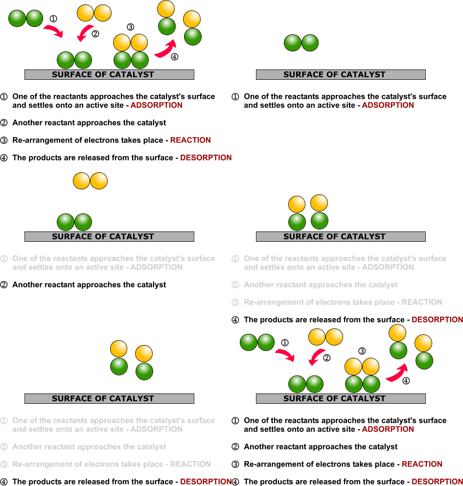
Examples of heterogeneous catalysisThe hydrogenation of a carbon-carbon double bondThe simplest example of this is the reaction between ethene and hydrogen in the presence of a nickel catalyst.In practice, this is a pointless reaction, because you are converting the extremely useful ethene into the relatively useless ethane. However, the same reaction will happen with any compound containing a carbon-carbon double bond.One important industrial use is in the hydrogenation of vegetable oils to make margarine, which also involves reacting a carbon-carbon double bond in the vegetable oil with hydrogen in the presence of a nickel catalyst.Ethene molecules are adsorbed on the surface of the nickel. The double bond between the carbon atoms breaks and the electrons are used to bond it to the nickel surface.

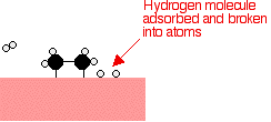
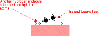
Hydrogen molecules are also adsorbed on to the surface of the nickel. When this happens, the hydrogen molecules are broken into atoms. These can move around on the surface of the nickel.

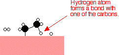
If a hydrogen atom diffuses close to one of the bonded carbons, the bond between the carbon and the nickel is replaced by one between the carbon and hydrogen.

That end of the original ethene now breaks free of the surface, and eventually the same thing will happen at the other end.

As before, one of the hydrogen atoms forms a bond with the carbon, and that end also breaks free. There is now space on the surface of the nickel for new reactant molecules to go through the whole process again.


Catalytic converters

Catalytic converters change poisonous molecules like carbon monoxide and various nitrogen oxides in car exhausts into more harmless molecules like carbon dioxide and nitrogen. They use expensive metals like platinum, palladium and rhodium as the heterogeneous catalyst.

The metals are deposited as thin layers onto a ceramic honeycomb. This maximises the surface area and keeps the amount of metal used to a minimum.

Taking the reaction between carbon monoxide and nitrogen monoxide as typical:

Catalytic converters can be affected by catalyst poisoning. This happens when something which isn’t a part of the reaction gets very strongly adsorbed onto the surface of the catalyst, preventing the normal reactants from reaching it.Lead is a familiar catalyst poison for catalytic converters. It coats the honeycomb of expensive metals and stops it working.In the past, lead compounds were added to petrol (gasoline) to make it burn more smoothly in the engine. But you can’t use a catalytic converter if you are using leaded fuel. So catalytic converters have not only helped remove poisonous gases like carbon monoxide and nitrogen oxides, but have also forced the removal of poisonous lead compounds from petrol.


The use of vanadium(V) oxide in the Contact Process

During the Contact Process for manufacturing sulphuric acid, sulphur dioxide has to be converted into sulphur trioxide. This is done by passing sulphur dioxide and oxygen over a solid vanadium(V) oxide catalyst.

This example is slightly different from the previous ones because the gases actually react with the surface of the catalyst, temporarily changing it. It is a good example of the ability of transition metals and their compounds to act as catalysts because of their ability to change their oxidation state.
The sulphur dioxide is oxidised to sulphur trioxide by the vanadium(V) oxide. In the process, the vanadium(V) oxide is reduced to vanadium(IV) oxide.The vanadium(IV) oxide is then re-oxidised by the oxygen.This is a good example of the way that a catalyst can be changed during the course of a reaction. At the end of the reaction, though, it will be chemically the same as it started.


c1


  1. C. G. Frost and L. Mutton, Green Chem., 2010, 12, 1687–1703 .
  2. M. Irfan, T. N. Glasnov and C. O. Kappe, ChemSusChem, 2011, 4, 300–316 
  3. C. F. Carter, I. R. Baxendale, M. O’Brien, J. P. V. Pavey and S. V. Ley, Org. Biomol. Chem., 2009, 7, 4594–4597 .
  4. P. McMorn and G. J. Hutchings, Chem. Soc. Rev., 2004, 33, 108–122.
  5. S. Ceylan and A. Kirschning, in Recoverable and Recyclable Catalysts, ed. M. Benaglia, John Wiley & Sons Ltd, 2009, pp. 379–410 .
  6. A. J. Sandee, D. G. I. Petra, J. N. H. Reek, P. C. J. Kamer and P. W. N. M. Van Leeuwen, Chem.–Eur. J., 2001, 7, 1202–1208 
  7. M. Pagliaro, V. Pandarus, R. Ciriminna, F. Belénd and P. D. Cerà, ChemCatChem, 2012, 4, 432–445 .
  8. C. W. Kohlpaintner, R. W. Fischer and B. Cornils, Appl. Catal., A, 2001, 221, 219–225 
  9. W. A. Herrmann, C. W. Kohlpaintner, H. Bahrmann and W. Konkol, J. Mol. Catal., 1992, 73, 191 
  10. A. B. Theberge, G. Whyte, M. Frenzel, L. M. Fidalgo, R. C. R. Wootton and W. T. S. Huck, Chem. Commun., 2009, 6225–6227 .
  11. A. Yoshida, X. Hao and J. Nishikido, Green Chem., 2003, 5, 554–557 .
  12. E. Perperi, Y. Huang, P. Angeli, G. Manos, C. R. Mathison, D. J. Cole-Hamilton, D. J. Adams and E. G. Hope, Dalton Trans., 2004, 2062–2064 .
  13. S. Liu, T. Fukuyama, M. Sato and I. Ryu, Org. Process Res. Dev., 2004, 8, 477–481 
  14. T. Fukuyama, M. T. Rahman, M. Sato and I. Ryu, Synlett, 2008, 151–163 
  15. J. F. B. Hall, X. Han, M. Poliakoff, R. A. Bourne and M. W. George, Chem. Commun., 2012, 48, 3073–3075 .
  16. R. A. Bourne, X. Han, M. Poliakoff and M. W. George, Angew. Chem., Int. Ed., 2009, 48, 5322 


//////

Share

How flow chemistry can make processes greener…………Supercritical fluids

 PROCESS, SYNTHESIS, Uncategorized  Comments Off on How flow chemistry can make processes greener…………Supercritical fluids
Jul 232015
 

Safe, small scale access to supercritical fluids

The ability to safely access high temperatures and pressures in flow reactors has implications not only on the rate of chemical reactions, but also on the types of solvents one can use. Many greensolvents such as methanol and acetone have boiling points too low for certain batch applications, whereas performing reactions at high pressure in a flow reactor may allow for their safe use at elevated temperatures.

Supercritical fluids are particularly interesting, since these solvents are entirely inaccessible without high pressure conditions. The use of supercritical fluids in a flow system offers numerous advantages over batch reactors.

Reactions may be performed on a small scale, improving safety and reducing the amount of material required. Depending on the type of reactor, it may be possible to visualize the reaction to evaluate the phase behaviour. Moreover, the reaction can be analyzed and the temperature and pressure subsequently changed without stopping the reaction and cleaning the vessel, as is necessary in a simple autoclave.
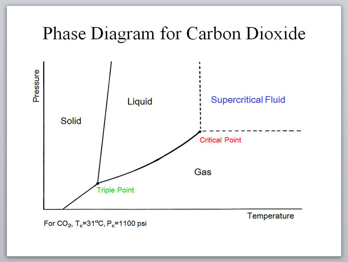
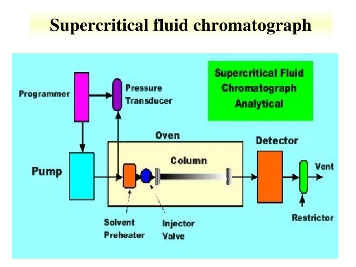
Continuous methods for utilizing supercritical fluids for extraction,1 chromatography,2 and as a reaction medium3 have all been commercialized, particularly for supercritical carbon dioxide (scCO2).4 Academic examples using scMeOH, scH2O, and scCO2 for continuous reactions such as hydrogenations, esterifications, oxidations, and Friedel–Crafts reactions have been reported.5

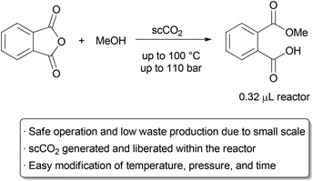
A recent example that illustrates many of the green advantages of performing supercritical fluid chemistry in flow is in the ring opening of phthalic anhydride with methanol by Verboom and co-workers (Scheme 1).6 They designed a microreactor with a volume of just 0.32 μL that can withstand very high pressures.
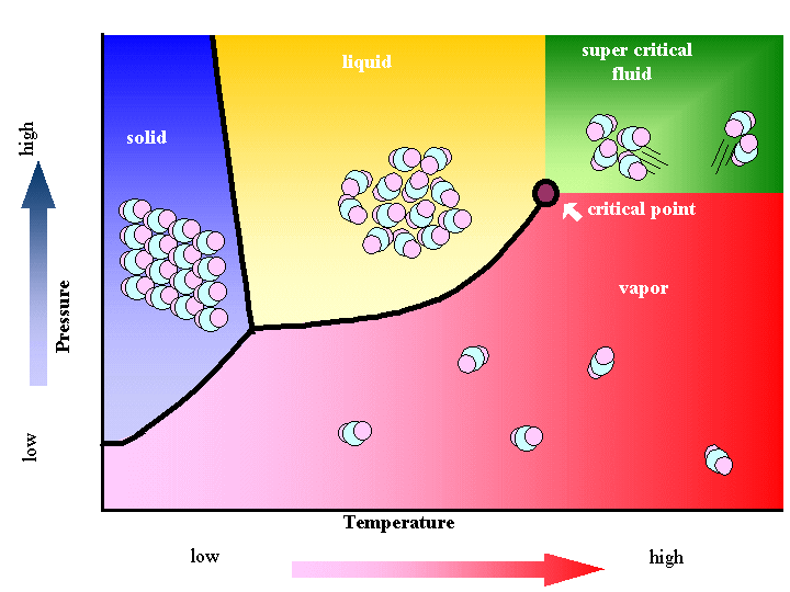
The exceptionally small channel causes a large build-up of pressure, and supercritical conditions with pressures of up to 110 bar and temperatures up to 100 °C can occur inside the reactor, giving an ‘on-chip’ phase transition. The channel size increases near the outlet, allowing the fluid to expand to atmospheric conditions.

Thus, the total volume of scCO2 under high pressure is exceptionally small, alleviating the major hazards of operating under supercritical conditions. The reaction was thoroughly studied on this small scale, allowing the authors to determine rate constants at several different temperatures and pressures.

Small scale continuous use of supercritical fluids.
Scheme 1 Small scale continuous use of supercritical fluids.

Near- and supercritical water (scH2O) can be an interesting green solvent only obtainable at very high temperature (Tc = 374 °C) and pressure (Pc = 221 bar). It is commonly used for completeoxidation of organic waste materials to CO2; however, it has also been shown to be an effective solvent for selective oxidations.7 Given the harshness of the reaction conditions, it is not surprising that side product formation is common and highly dependent on the reaction time. For fast reactions in a batch reactor, precise control of reaction time is challenging, as the vessel takes time to heat and cool. In contrast, rapid heating, cooling, and quenching can be accomplished in a continuous process, allowing for well defined reaction times.

Fine tuning of the temperature, pressure, and time is also easier in a continuous process, as these variables can be changed without stopping and starting the reaction between samples. Thus, more data points can be obtained with less material and fewer heating and cooling cycles.
The Poliakoff group used these advantageous to perform a detailed study on the oxidation of p-xylene to terephthalic acid in scH2O, a reaction carried out on industrial scale in acetic acid (Scheme 2).8 By using a flow reactor, reaction times as low as 9 seconds could be used. The equivalents of oxygen could also be finely varied on a small scale through the controlled thermal decomposition of H2O2.

Studying this aerobic oxidation with such precision in a batch process would prove highly challenging. Under optimal conditions, excellent selectivity for the desired product could be obtained. Further research by the same group identified improved conditions for this transformation.9

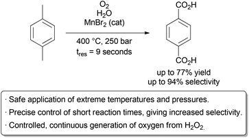
Selective oxidation in supercritical water.
Scheme 2 Selective oxidation in supercritical water.


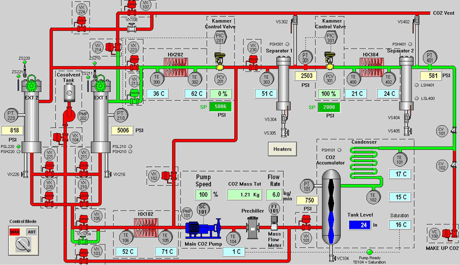
Schematic Diagram of sample Supercritical CO2 system

Table 1. Critical properties of various solvents (Reid et al., 1987)
Solvent Molecular weight Critical temperature Critical pressure Critical density
g/mol K MPa (atm) g/cm3
Carbon dioxide (CO2) 44.01 304.1 7.38 (72.8) 0.469
Water (H2O) (acc. IAPWS) 18.015 647.096 22.064 (217.755) 0.322
Methane (CH4) 16.04 190.4 4.60 (45.4) 0.162
Ethane (C2H6) 30.07 305.3 4.87 (48.1) 0.203
Propane (C3H8) 44.09 369.8 4.25 (41.9) 0.217
Ethylene (C2H4) 28.05 282.4 5.04 (49.7) 0.215
Propylene (C3H6) 42.08 364.9 4.60 (45.4) 0.232
Methanol (CH3OH) 32.04 512.6 8.09 (79.8) 0.272
Ethanol (C2H5OH) 46.07 513.9 6.14 (60.6) 0.276
Acetone (C3H6O) 58.08 508.1 4.70 (46.4) 0.278
Nitrous oxide (N2O) 44.013 306.57 7.35 (72.5) 0.452

Table 2 shows density, diffusivity and viscosity for typical liquids, gases and supercritical fluids.

Comparison of Gases, Supercritical Fluids and Liquids
Density (kg/m3) Viscosity (µPa∙s) Diffusivity (mm²/s)
Gases 1 10 1–10
Supercritical Fluids 100–1000 50–100 0.01–0.1
Liquids 1000 500–1000 0.001
  1. F. Sahena, I. S. M. Zaidul, S. Jinap, A. A. Karim, K. A. Abbas, N. A. N. Norulaini and A. K. M. Omar, J. Food Eng., 2009, 95, 240–253
  2. D. J. Dixon and K. P. Jhonston, in Encyclopedia of Separation Technology, ed. D. M. Ruthven, John Wiley, 1997, 1544–1569
  3. P. Licence, J. Ke, M. Sokolova, S. K. Ross and M. Poliakoff, Green Chem., 2003, 5, 99–104
  4. X. Han and M. Poliakoff, Chem. Soc. Rev., 2012, 41, 1428–1436
  5. S. Marre, Y. Roig and C. Aymonier, J. Supercrit. Fluids, 2012, 66, 251–264
  6. F. Benito-Lopez, R. M. Tiggelaar, K. Salbut, J. Huskens, R. J. M. Egberink, D. N. Reinhoudt, H. J. G. E. Gardeniers and W. Verboom, Lab Chip, 2007, 7, 1345–1351
  7. R. Holliday, B. Y. M. Jong and J. W. Kolis, J. Supercrit. Fluids, 1998, 12, 255–260
  8. P. A. Hamley, T. Ilkenhans, J. M. Webster, E. García-Verdugo, E. Vernardou, M. J. Clarke, R. Auerbach, W. B. Thomas, K. Whiston and M. Poliakoff, Green Chem., 2002, 4, 235–238
  9. E. Pérez, J. Fraga-Dubreuil, E. García-Verdugo, P. A. Hamley, M. L. Thomas, C. Yan, W. B. Thomas, D. Housley, W. Partenheimer and M. Poliakoff, Green Chem., 2011, 13, 2397–2407

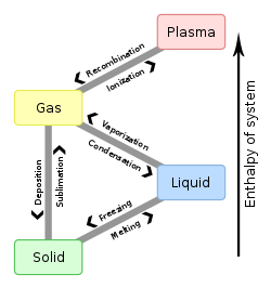
Phase change - en.svg


सुकून उतना ही देना प्रभू, जितने से जिंदगी चल जाये। औकात बस इतनी देना, कि औरों का भला हो जाये।
DRUG APPROVALS BY DR ANTHONY MELVIN CRASTO …..FOR BLOG HOME CLICK HERE

Join me on Linkedin

View Anthony Melvin Crasto Ph.D's profile on LinkedIn

Join me on Facebook FACEBOOK

Join me on twitterFollow amcrasto on Twitter
Join me on google plus Googleplus

 amcrasto@gmail.com

09b37-misc2b027LIONEL MY SON
He was only in first standard in school when I was hit by a deadly one in a million spine stroke called acute transverse mylitis, it made me 90% paralysed and bound to a wheel chair, Now I keep him as my source of inspiration and helping millions, thanks to millions of my readers who keep me going and help me to keep my son happy
सुकून उतना ही देना प्रभू, जितने से
जिंदगी चल जाये।
औकात बस इतनी देना,
कि औरों का भला हो जाये।


Share
Follow

Get every new post on this blog delivered to your Inbox.

Join other followers: